This thread has been locked.

If you have a related question, please click the "Ask a related question" button in the top right corner. The newly created question will be automatically linked to this question.

I need ADC board/device with USB output and Linux driver/software

Other Parts Discussed in Thread: INA849, PCM2906C, PCM2903C, PCM2904, PCM2901, PCM2912A, TLV320ADC5120, PCM2903EVM-U, REG1117

Hi!

I am not sure which forum analog-to-digital converters belong to, so here comes my question:

I have built an instrumentation amplifier using the INA849 chip.

Now I need to digitize the output signal and get it into my Ubuntu Linux PC (via a USB port), in a way where I can record the signal and save it to a standard file-format for later analyzing.

I can probably use the Audacity software for the recording and saving, if the device has a Linux driver.

I can see a large amount of ADCs here: https://www.ti.com/data-converters/adc-circuit/products.html

But I am not sure how to find what I am looking for.

Note: I need at least 2 channels and at least 16 bit samples.

To begin with I need to sample the audio spectrum (approximately 0-20.000 Hz), but it would be nice if the board/device can go much higher, maybe 100 KHz or 400 KHz, and it would be very nice if there is some kind of frequency-adjustable, effective low-pass filter before the digitalization.

I look forward to hear from you.

Thank you.

  • Hi Henrik,

    Here's our catalog of USB audio converters: https://www.ti.com/audio-ic/converters/usb/products.html

    The PCM2906C would be a good place to start. There's no Linux drivers for these parts since they aren't configurable over I2C or anything like that. They operate through HID and USB interface. Also the bandwidth is limited to the audio range (20Hz-20kHz).

    Let me know if you have any questions,
    Jeff McPherson

  • Great. Thank you.

    I have looked at the catalog. I find it a bit difficult to detect the differences between 6 of the 7 chips? Except that it seems that some of them are powered by the USB connection and others need there own power supply(?)

    What are the motives for some of the chips needing a separate power supply? Is it because having their own power supply makes it possible to give them a better power supply that enables them to create a better quality output? And is this true both for the ADC and the DAC?

    I was looking at PCM2903C, but it seems the EVM only allows using the DAC, not the ADC?

    Do you have any ADCs that can adapt to the analog input signal level - in other words a kind of built-in adapting amplifier that amplifies the analog input signal so that the digital output utilizes most of the 16 bit bandwidth?

    I look forward to hear from you. Thank you.

  • Hi Henrik,

    The PCM290xC parts are all part of the same family. Their differences are in this table below. The PCM2904 and PCM2901 are previous generations of the PCM290xC parts but are still perfectly fine to use. The PCM2912A allows for mixing the analog input signal with the DAC output.

    Yes the idea of using a separate power supply over the bus-powered supply is if a cleaner power supply is available. This is true for both ADC and DAC.

    The PCM2903C EVM has input and output jacks, allowing for both ADC recording and DAC playback.

    The feature you're describing does exist in some of our other standalone ADCs however they don't have USB support integrated into them. They output I2S signals. If you're interested you can take a look at the TLV320ADC5120 and look for the "Dynamic Range Extender" function.

    Best regards,
    Jeff McPherson

  • Thank you!

    The quality of the digital output signal via USB to the Linux PC is quite important, so I prefer a separate power supply, which means choosing the PCM2903C and thus the PCM2903EVM-U.

    Since I don't need the S/PDIF in/out I guess I can choose between using a 5V or a 3.3V power supply?

  • I have looked at the 3.3V voltage regulator - https://www.ti.com/product/REG1117 . It seems to regulate and stabilize the voltage quite a lot, so I guess it's an advantage to supply the 5V.

  • Why does TI.com NOT want to sell me the PCM2903EVM-U ?

    30 min. after ordering, TI cancelled it. And the order history does not state any kind of reason for this. Just:

    Order status: Cancelled
  • Luckily other electronics distributors are keen on selling to me...!

  • Hi Henrik,

    The device supports a supply voltage of only 3.3V. This is is section 7 of the datasheet under "Recommended Operating Conditions."

    Which region/nation are you trying to ship the EVM to?

    Thank you,
    Jeff McPherson

  • According to the PCM2903EVM-U documentation:

    "The PCM2903EVM-U requires a 5-V power supply for the codec and S/PDIF sections and a 5-V power
    supply for the analog input/output amplifier section."

    The board has a REG1117 3.3V regulator/converter that supplies the ADC/DAC chip.

    I live in Denmark.

  • Hi Henrik,

    I see, I misunderstood your first comment then. 

    There should be no issues with Denmark and I see there's stock available. Can you try to resubmit the order? If it fails again, let me know if there are any other TI emails included or CC'd.

    Thank you,
    Jeff McPherson

  • I chose to buy from Mouser instead.

  • Questions about the 5V power supply to the PCM2903EVM-U:

    As far as I can tell, the PCM2903C chip itself uses max. 70 mA, 3.3V.

    But I can't find any data on how much the whole PCM2903EVM-U uses?

    In order to get a stable low noise power supply I was thinking to use a (rechargeable) battery. But choosing the right battery depends on how much current or watt the PCM2903EVM-U will use?

    And what power supply voltage interval does the nominal "5V" actually mean?

  • Hi Henrik,

    The EVM when idle consumes about 70mA. If you add the 70mA + margin for the max consumption stated in the data sheet, I'd expect 150mA to be the highest consumption you'd have to support.

    Since the 5V supply directly goes through the LDO, the LDO defines the voltage tolerance. The input voltage can drop to as low as 4.4V before you see a 1% drop in the output. In the other direction, the input can go as high as 15V. 

    Best regards,
    Jeff McPherson

  • Great. Thank you. :-)

  • But since the "5V" goes directly to the S/PDIF in and out on PCM2903EVM-U, what would happen to them if it is up to 15 V in practice?

    Another question:

    I don't really understand the meaning of the 6 jumpers called CN002 on the PCM2903EVM-U board?

    I cannot see any explanation of their functions. (The "5V" power supply to S/PDIF in and out does not go through any of those jumpers.)

  • I see. I missed the connection to the SPDIF connectors. According to their data sheet, the acceptable voltage range is 4.75V - 5.25V. That overrules the limitations of the buck converter.

    As for the jumpers, the user guide is missing the descriptions, but you can find their connections in the schematic at the end of the user guide. They connect things such as the SPDIF input/output, voltage supplies, the SEL0 and SEL1 inputs, etc.

    Best regards,
    Jeff McPherson

  • Is there no way to cut the power to the S/PDIF in and out so I can raise the voltage of my power supply? That would be quite practical.

  • Hi Henrik,

    Unfortunately there is no way to simply remove power, since it's supplied via trace, not through the CN002 jumpers. If you don't need the SPDIF connections and would like to supply a higher voltage, I would simply lift them from the board.

    Best regards,
    Jeff McPherson

  • OK. Thanks. I will try that. :-)

  • A comment on the design of the EVM:

    Now that the signals to and from the SPDIF goes through jumpers, I think it would be logical and smart if the power supply for the SPDIF was also through a jumper. :-)

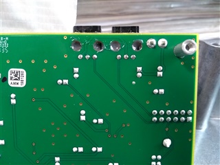
  • OK. Now that the power to the SPDIF In and Out connectors cannot be disconnected via the jumpers, you suggest that I 'lift them off the board'. But as you can see on this photo, they are glued to the board. So is this some special glue that I can dissolve? And how?

    Or can I de-solder and thus de-connect the power (+) pin on them?

    SPDIF in and out are glued on

  • Hi Henrik,

    I wasn't aware of the glue. Simply de-soldering the connection is enough to remove power to the SPDIF connector. I only mentioned lifting since it would be easy if the glue wasn't there.

    Best regards,
    Jeff McPherson

  • I tried heating the solder to about 300-350 degrees Celsius and remove it with a desoldering gun like this:

    It didn't work. I also don't know if the tiny capacitors on the board can take about 14V? I guess I will have to find a 4.75V - 5.25V power supply instead.

  • Hi Henrik,

    All of the caps can take at least 16V. But if removing the connection is too much of a struggle, yes I would go with the power supply originally intended by the EVM.

    Best regards,
    Jeff McPherson