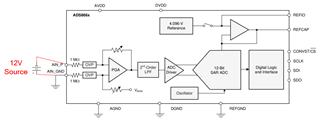
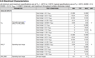
When I read the datasheet, I see that AIN_P and AIN_GND pins are designated for positive input. I want to provide a negative input in bipolar mode. How should I make the connections?

-
Ask a related question
What is a related question?A related question is a question created from another question. When the related question is created, it will be automatically linked to the original question.


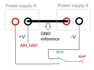
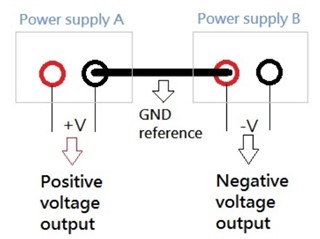 here is my power supply. how can I connect to ADC GND reference pin and negative voltage output pin?