This thread has been locked.

If you have a related question, please click the "Ask a related question" button in the top right corner. The newly created question will be automatically linked to this question.

ADS1114-Q1: ADS1114-Q1

Part Number: ADS1114-Q1
Other Parts Discussed in Thread: ADS1148, ADS1248, ADS1114, ADS1115, ADS1115-Q1, ADS131B23-Q1

Hello,

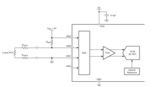
I would like to ask for help. I have a 2 wire RTD on my PCB completely for safety. It means I measure the resistance via delta-sigma precision ADC and I need to set a limit temperature where I produce an ALARM signal if the temperature on the RTD reaches the threshold value. Therefore I would prefer a delta-sigma with an inbuilt comparator and preferably a chip with a functional safety category. Is it possible to use this chip for RTD measurment, if yes is there a reference circuit to use? Could you please suggest a good solution for this design, to measure 2 wire RTD an generate an ALARM signal if the temperature is higher than the set value.

Thank you for your help.

Zsolt

  • Hello Zsolt,

    The ADS1114-Q1 would work for this, but you will need to provide a current source somehow. Here is a reference design that shows you how to do this for a space-grade device: https://www.ti.com/lit/ug/tiduf19/tiduf19.pdf. You could adapt this for use with our usual devices. This other design demonstrates the general design of a 2-wire RTD measurement system: https://www.ti.com/lit/an/sbaa329a/sbaa329a.pdf?ts=1707240253676 

    If you can implement the ALERT functionality in a microcontroller, you should consider the ADS1120-Q1, which integrates the current source, sparing you the trouble of implementing the current source with an op-amp.

    Let me know if you have any more questions,

    Levi DeVries

  • Hello Levi

    Thank you for your reply, and the reference designs its a great help. Could you please suggest a design how to realize the ALARM circuitry?

  • Zsolt,

    There are example schematics on how to use the alarm pin in the datasheet on page 30: 

    As you can see, the ADS1114-Q1 alert pin should be connected to a GPIO pin on your microcontroller so that it can trigger an interrupt. The alert line should also have a pull-up resistor as shown in the diagram on page 30 (above)

    Let me know if you have aby more questions,

    Levi DeVries

  • Hi Levi,

    Thank you very much for you help. Can I use this chip for 2-wire RTD? If yes could you send me an application note how?

    Thank you in advance.

    Zsolt

  • Hi Zsolt,

    Yes, this device can be used to measure a 2 wire RTD and generate an ALARM signal.

    Like Levi previously mentioned, with ADS1114 you would have to supply your own excitation current source, while other devices such as the ADS1148 and ADS1248 have this feature integrated. 

    The following app note: A Basic Guide to RTD Measurements (Rev. A) (ti.com) gives an overview of 2-wire, 3-wire, 4-wire RTD wiring configurations and shows the basic topology of a ratiometric measurement. 

    The following app note: RTD Ratiometric Measurements and Filtering Using the ADS1148 and ADS1248 (Rev. A) covers how to make RTD measurements configured in a ratiometric topology using the built-in IDAC current sources feeding through an external reference precision resistor. The ratiometric operation has an advantage because the errors due to the excitation current source drift and noise tend to cancel. 

    Our TIPL series: Precision labs series: Analog-to-digital converters (ADCs) | TI.com covers this topic in detail as well in the section "Measuring RTDs with presicion ADCs".

    Best Regards,

    Angel

  • Hi Angel,

    Thank you very much for your help. Can I have 1 more question? Is it possible to use for my application the new Functional Safety Compliant 24 bit ADC chip the ADS131B chip? If yes how can I realize a two wire RTD with it?

    Thank you, have a nice day

    Zsolt

  • Hi Zsolt,

    What are your functional safety compliance requirements? 

    Using ADS131B would add a lot of extra complexity.

    You should make a new E2E post on ADS131B if you want details about this device.

    Best Regards,

    Angel

  • Hi Angel,

    My Performance level is B, my SIL is 2.

    Thank you, have a nice day

    Zsolt

  • Dear Zsolt,

    my colleagues brought your request to my attention. I am the functional safety manager within the precision ADC team. Let me see if I can help you out.

    I believe we can address your needs with the ADS1115.
    The ADS1115 was not developed according to TI's process for the development of functional safe hardware, however the device is relatively simple, so that we should be able to get away with some basic information.
    For the ADS1115-Q1 we released a document on the product folder which shows the FIT rate, failure mode distribution and pin FMA for the device. The same data and information applies to ADS1115 as well. Following the link to the document: ADS1115-Q1 Functional Safety FIT Rate, FMD and Pin FMA

    We can use that information to populate your FMEDA and then define certain safety mechanisms which you can implement to detect the various faults.

    As you are measuring a simple 2-wire RTD, I would propose using voltage excitation. For your specific case I would suggest to use a precision voltage source (e.g. an external voltage reference) with e.g. 4.096V output to excite a resistor divider consisting of the RTD and a precision bias resistor as shown in below simplified diagram (RC filters, etc. are not shown).

    The RTD resistance can be calculated from measuring the voltage across the RTD.
    V_RTD = R_RTD / (R_RTD + R_BIAS) x V_REF.

    You can solve that equation for R_RTD. Both V_REF and R_BIAS are known and their accuracy will determine the accuracy of your measurement.

    Now looking at the functional safety aspect. We can implement the following safety mechanisms (SMx) to address the various failure modes of the ADS1115:

    • SM1: Reference voltage measurement
      Measure the reference voltage using the Mux connection (AIN2 - GND).
      This measurement can be used to measure the accuracy of the ADC. It would therefore address the failure modes offset error, gain error and I would say also output code error to some extend.
      This measurement can also be used to detect a stuck-at Mux or if the Mux selected a wrong channel to some extend.
    • SM2: Offset voltage measurement
      Measure the ADC offset using the Mux connection (AIN1-GND) or short AIN3 to GND externally and measure (AIN3-GND).
      This measurement addresses the offset error fault and the output code error to some extend.
    • SM3: Read conversion data multiple times
      You can read every conversion data multiple times to detect if there was any communication error during the conversion result read.
    • SM4: Read back register settings
      By reading back the register settings you can detect if there was any communication error during a register write operation.
    • SM5: Diagnostic of ALERT pin
      The ALERT pin not tripping would usually be considered a latent fault and doesn't directly violate the safety goal. In order to detect if the ALERT pin is still functional, you could periodically change the threshold setting of the comparator and trip the ALERT output on purpose.

    Next you would also have to look at the failure modes due to pin faults, determine which ones would violate your safety goal, and then come up with an according safety mechanism. Likely the above mentioned SMs could be used to detect most pin faults.

    In addition you may also need external supply voltage monitors to detect if the ADC supply is out of range.
    Potentially you could get away with measuring the supply using the ADS1115 itself and the measurement of the reference voltage. If one of those two measurements is off, it would be a pretty good indication that something (e.g. the supply) is not correct.

    Detecting if the RTD is disconnected is usually required as well. This should be relatively easy to detect, because the voltage across the RTD would equal the reference voltage in that failure condition.

    The ADS131B23-Q1, while developed using TI's process for the development of functional safe hardware, would seem like a lot of overkill for your application. But it could certainly be used as well.

    Regards,
    Joachim Wuerker

  • Dear Wurker,

    Thank you very much for your valuable post, I really appreciate it, it is already a great help in terms safety prooved design. If I have the possibility to ask directly from a Safety expert I would like to grab this opportunity.

    Which safety safety standards one must follow IEC 61508 (SIL levels) or the ISO 13849 (Performance levels)?

    If I use an ADC chip without the dedicated Alert pin is SM1-5 still enough or do I need a second HW relevant safety relevant circuitry?

    Does it matter whether I use I2C or SPI?

    If I use the chip ADS131B23-Q1, which as you said might be an overkill, Can I use 1 chip for 2 separated (both on the same GND) 2-wrire RTD on my board?

    If I use the chip ADS131B23-Q1, I assume only SM3-5 steps need to be done, or?

    If I use the chip ADS131B23-Q1, is there a reference design available?

    I use the uController from Microchip a Pic24, do I need other measures like a Watchdog, or any other device to monitor the uController?

    Once again Thank you for your time and help.

    Zsolt

  • Dear Zsolt,

    you are very welcome.

    Which safety safety standards one must follow IEC 61508 (SIL levels) or the ISO 13849 (Performance levels)?
    I would say this depends on the application/market/end equipment you are targeting. Your end customer or your functional safety manager should be able to tell you. As you are doing a functional safety design, I assume you have a functional safety manager within your company.

    If I use an ADC chip without the dedicated Alert pin is SM1-5 still enough or do I need a second HW relevant safety relevant circuitry?
    This really depends on your safety requirements and your fault reaction time requirements.
    In my opinion an Alert pin would not be required unless you need to detect an overtemperature faster than you can read it out from the ADC.

    Does it matter whether I use I2C or SPI?
    I don't think so.

    If I use the chip ADS131B23-Q1, which as you said might be an overkill, Can I use 1 chip for 2 separated (both on the same GND) 2-wrire RTD on my board?
    I would think so. You would use one ADC from section A for one RTD, and one ADC from section B for the other RTD. Unless the two RTD measurements don't need to be independent.

    If I use the chip ADS131B23-Q1, I assume only SM3-5 steps need to be done, or?
    With ADS131B23-Q1 you have to detect similar faults, the way they are being detected differs however from the way you would do it when using a single ADS1115-Q1.
    Please refer to the Functional Safety Manual, which you can request on the product folder.
    Here is the direct request link: https://www.ti.com/licreg/docs/swlicexportcontrol.tsp?form_id=307127&prod_no=ADS131B23-Q1&ref_url=asc_dc_padc

    If I use the chip ADS131B23-Q1, is there a reference design available?
    Maybe looking at the Safety Manual would be a good starting point for that.

    I use the uController from Microchip a Pic24, do I need other measures like a Watchdog, or any other device to monitor the uController?
    In the end you will have to determine the various faults of the uC and then determine which ones are safety relevant. For faults that violate your safety goal you will have to mitigate or prevent them with certain measures.

    Regards,
    Joachim Wuerker