Hello,
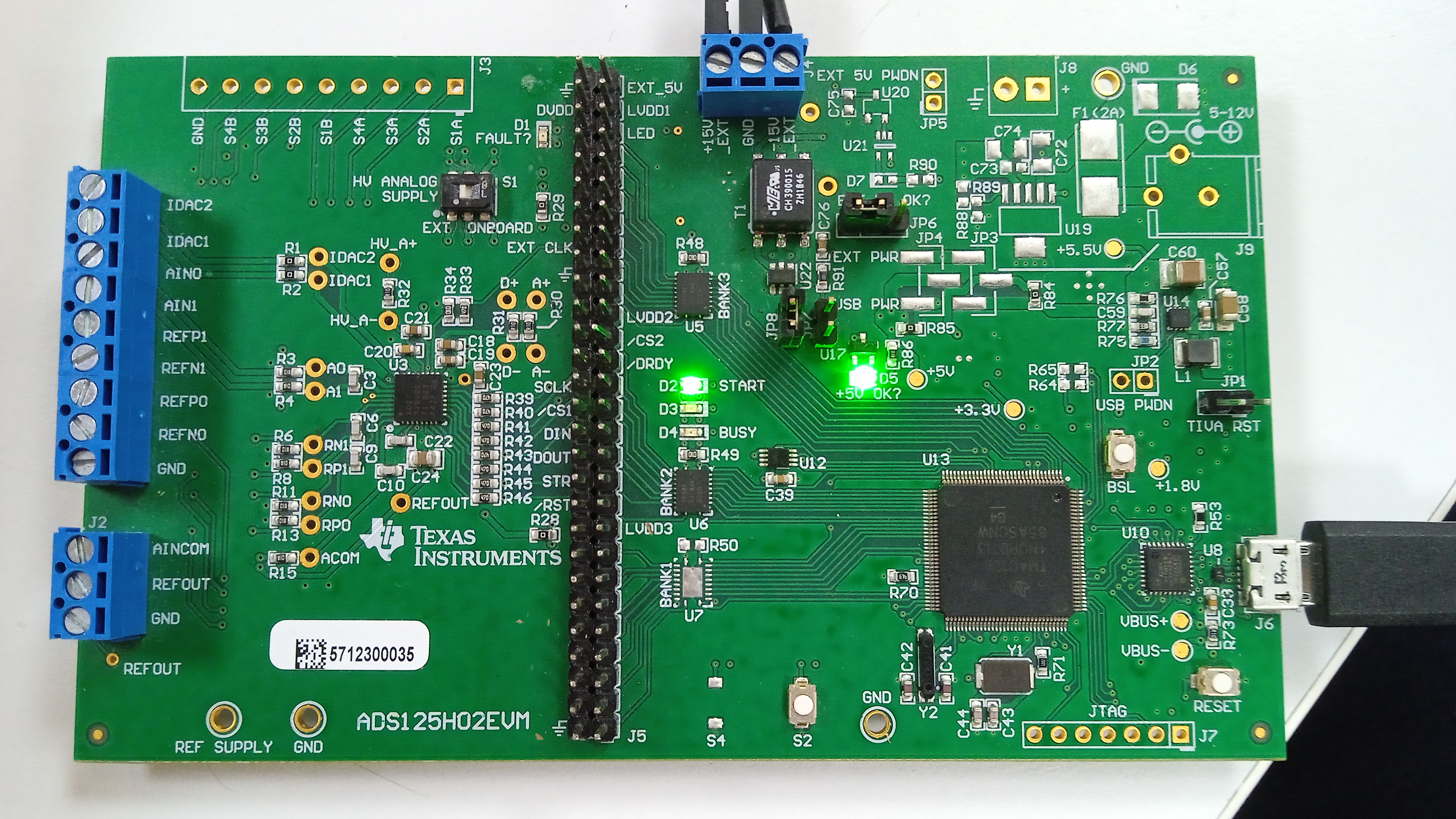
I am trying to use ADS125H0EVM evaluation board. I followed the instructions to download GUI then later downloaded the device package to a public path.
Driver:
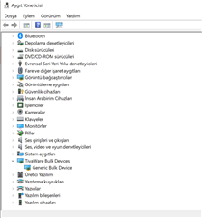
Drivers path:
C:\Program Files (x86)\Texas Instruments\DSEvalSW
Device packages path:
C:\Users\admin\Documents\DSEvalSW
When I start the GUI first and connect the EVM board afterwards, the GUI will not recognise the board.
When I conect the board first and start then the GUI software, I receive the message "Unable to Identify device = An" and after a few seconds: " Hardware Connected. Ready..."
The registers are not displayed.
In the console section there is an error message:
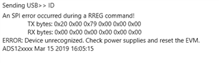
What should I do?