This thread has been locked.

If you have a related question, please click the "Ask a related question" button in the top right corner. The newly created question will be automatically linked to this question.

ADS114S08B: 6x RTD measurement

Part Number: ADS114S08B
Other Parts Discussed in Thread: ADS124S08

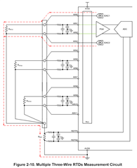
I have to measure 6 RTD's with 3 wire topology, typical application reccomends to use 4 AINs per one RTD (2 for IDC and 2 for AI), which means I have to use external multiplexer or second ADS14S08B. Is it possible to configurate internal multiplexer to use that same AIN for current sourcing and voltage measurement simultaneously? Are they any disadvantages of that kind of solution if it is possible? 

  • Hi Wojciech Stepniak,

    Below is how you would architect the circuit you are describing, at least 3x RTD measurements using 1x ADC. This is from our RTD Design Guide: https://www.ti.com/lit/an/sbaa275a/sbaa275a.pdf?ts=1709157991209&ref_url=https%253A%252F%252Fwww.google.com%252F

    The ADS124S08 can output the current on the same pin as the measurement input, but you should not do this for RTD measurements. As you can see in the image below, there is an anti-aliasing filter made up of a resistor and a capacitor on the measurement channels e.g. AIN1 and AIN2. If you output the current on the measurement channel e.g. AIN1, instead of a separate channel e.g. AIN0, then the current flows through this filter resistor, which generates a voltage. If the current sources (IDACs) were 100% matched and the resistors were perfectly ideal, then this would not be an issue. Since this is not the case, there will be some error associated with this configuration, which can be significant. We would not recommend this as a solution for you. Instead, using two ADCs is likely the best option because then you are just creating one circuit and replicating it several times. Using lots of multiplexers can be complicated in terms of routing and control, but it is certainly possible. But you will likely need 8-ch muxes as there are not that many 6-ch muxes

    -Bryan

  • Thank You Bryan, 

    I've read this article before, nevertheless, I wanted to ask about another possibilities, because with 2 ADCs I'll have most probably problem with space on the PCB. 

    Youv'e mentioned the case of anti-aliasing filter, the imputs for the RTD has to be protected against bursts and surges. Thera are a few ways to do it, but it includes series resistance on the imputs and parallel capacitance and/or TVS diodes (TVS diode without series resistance which limits current won't help from my experience). That solution will affect the measurement, that same way You desribed with anti-aliasing filter. If I do not protect the AINs and especially current sources they will most probably be disturbed from bursts or destroyed by surges. I was looking for a some destription about it, but I've found only recomendation for the analogue inpunt's without current sources (eg. voltage measurement etc).

    Do You have any recommendations about it? 

  • Hi Wojciech Stepniak,

    The IDAC channels will indeed need to be protected if you expect transient / surge voltages in your system. Some systems are closed such that this is not a requirement for all designs i.e. these components are not strictly required.

    If you do need them, then a current limiting resistor is the bare minimum for the IDAC channel. However, since this resistor is not in the measurement path it will not result in an error. The TVS diodes will have a leakage current that will cause an error, but typically this is on the order of 10's of nA, whereas the IDAC current is 100s of uA (or more), resulting in a much larger error. You can review our Precision Labs content for more information. Review the video series called "Protecting ADCs from electrical overstress (EOS)", specifically the videos shown in the image below

    https://www.ti.com/video/series/precision-labs/ti-precision-labs-analog-to-digital-converters-adcs.html

    -Bryan

  • Dear Bryan Lizon, 

    I've watched all of those tutorials but there are only informations I already know. The first one on the list You send: 

    doesn't say anything about protecting and in case of RTD, it explains the idea of RTD measurement (just like a sbaa275a). 
    after all of those, I still, know how to protect AINs for measurement's and still don't know how to protect AINs used as IDACs. 

    What I'm thinking of is protecting IDACs and AINs like this: (its only a first draft) 

    but I'm not sure if it's enough to withstand 4kV (8/20) surge wave, and also be immune for the fast transients (EFT) 2kV, 5kHz.

  • Hi Wojciech Stepniak,

    Are you sure you watched all of the videos? The second video specifically discusses how to protect the input pins including the IDAC channel, as shown in the image below. The 4th video calculates the performance impact of the TVS diodes on the overall measurement. I would suggest reviewing all of the material I suggested. It seems like you may have only watched the first video.


    -Bryan

  • Hi Bryan Lizon, 
    thank You, I've watched 4 videos prior to "protecting Delta-Sigma ADC: RDT Overview 

    now I've watched everything else and know everything I wanted. I didn't expect to be possible to choose as high values of the Rp (in series in IDAC's line). 

    Thank You once again, that solved my problem.

    I wish You good day! 

  • Hi Wojciech Stepniak,

    I am glad the other videos helped you

    Note that the resistance in the IDAC line can be large if desired, this is dependent on the IDAC compliance voltage. This is explained in the video "Protecting Delta Sigma Component Selection"

    -Bryan