DAC8775: 16-Bit Quad-Channel Programmable Current-Output and Voltage-Output Digital-to-Analog Converter

Part Number: DAC8775

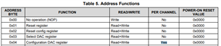
The DAC8775 channels seem to share the same configuration registers. Is it true?

In my application, if I have four channels of D/A outputs, two are current and the other two are voltage outputs with different ranges. How can I accomplish this type of application goals?

  • Max,

    The DAC8775 DAC channels can be independently set for different outputs. You can use the Select DAC register (0x03) to select the DAC channel you want to write to. After that, you can then write to the Configuration DAC register (0x04). You would do this for each channel you select with 0x03.

    If want to test this, I highly recommend getting a DAC8775EVM to test the operation. 

    Joseph Wu

  • Hi Joseph,

    I can manipulate each individual channels as you just adviced. However, my conventional understanding is that once the Configuration DAC register (0x04) is configured, its settings should be retained forever. You do not need to write it (0x04) every time before you write the DAC data output.  

    Is it possible that I only configure the 0x04 register once during the initialization and then just do "select 0x03 register, output DAC value to 0x05", etc?

    Additional question--those dac channel calibration enable (0x08), dac channel gain calibration(0x09), dac channel offset calibration(0xa) registers are chip-wide regisers or just for channel-based registers (which means the user must set those registers for each individual channel)?

    Thank you so much!

    Max 

  • Max,

    You can just configure the 0x04 register once, but it is set on a per channel address. If you look at page 47 of the datasheet, there is a  Table 5 for Address Functions. In that table, there is a column that shows the configuration per channel (4th column). Register 0x04 is set per channel, so that these settings in the register are done when you have the 0x03 register used for selecting the channel. This is explained on the next page, at the top of page 48.

    The image of the table is below, along with a clipped out section of text after the table.

    Joseph Wu

  • I can independently control the channel output now. Thanks for your help!

    However, if I set the RANGE[3:0] in configuration DAC register to be +/-10V or +/-12V, the corresponding channel will have a fault bit set in DAC status register. Other voltage settings seem to be ok. Anything do I need to pay attention particularly for this?

    Max


  • Max,


    Is the status but set positive in one of the bits for register 0x0B? Which bit is setting the alarm in the register? Is it one of the bits for FA to FD?

    I believe this is likely one of the faults set by the alarms listed in section 8.3.8 on page 40. The alarms occur with different problems with the IOUT voltage, an IOUT open circuit, the die temperature, SPI timeout or CRC error, short circuit current limit, or the buck-boost converter reaching a maximum voltage.

    Because this occurs using a voltage setting, this might be an issue driving too large of a capacitance. With a capacitive output and a large signal change, the capacitance might be seen by the device as a instantaneous short, as the output voltage slowly rises to fill the capacitance. Can you check the device's capacitive load and then remove any spare capacitance to test the output? This might be enough to quickly raise the output, to fool the part that the output isn't a momentary short.


    Joseph Wu

  • Hi Joseph, 

    Another issue---If I write a 0x0000 to the DAC output data register, then write 0xffff to the DAC chip to ramp up the output. However, if I immediately read back the DAC output data register (e.g in 50us), I can't get the exact 0xffff back. Is that reasonable?

    Max

  • Max,


    Can you describe the device setting when you read back the DAC output data register? There are a couple of settings that might affect the DAC output data register setting.

    For example, if you have the device set to a slew rate mode, the DAC output transitions from an initial value to a final value through several calculated intermediate points. The DAC output data register write will be the final settled value for the DAC output transition. However a read back of the register will give the current intermediate value of the DAC output in transition.

    Because of the slew rate mode setup, then DAC output data register may not be the value that was written into the device. It will however, reach that the final value once the slew transition occurs.


    Joseph Wu

  • Hi Joseph,

    Your explaination confirms my observation. Indeed, I set every channel with the slew rate. No wonder the instant read back did not match my writing value.

    Thank you very much!

    Max