AMC131M03: Is it possible to cut off the dc voltage.

Part Number: AMC131M03
Other Parts Discussed in Thread: ADS131M03

Hi

My customer is developing an 11kw electric vehicle AC charger.

1. There is a dc voltage cut-off test in Korea's charger certification, so can I cut-off using AMC313M03?

2.Has AMC131M03 been applied to 11KW charger certification ever passed?

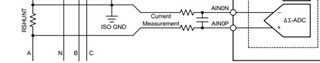
3.For your reference, I used SHUNT resistance, can I change it to CT and apply it?

4. The charger should have an LED light indicating the status, can I control it with AMC131?

Thanks

  • Hi David,

    1.  I'm unsure on the specifics of your dc voltage cutt-off test, could you provide some more info on that?  You should be able to measure the DC voltage and take corrective action at some cut-off voltage using the AMC131M03.

    2.  This device is very new and still in the design/test phase for most customers.

    3.  It is possible to use a CT.  Though the CT already provides isolation, so you would probably feed it's output into the non-isolated version of this device: ADS131M03.  You would also need to discretely isolate any other inputs before feeding it into the other 2 channels of the ADS131M03.  

    4.  I'm not sure how you intend to control the LED.  The AMC131M03 is a 3-channel isolated adc that can measure 3 channels simultaneously and provide those measurements through a SPI interface.  Typically a MCU is used to communicate with the AMC131 device and read the measurements, so you could control an LED status with the MCU based on the measurement readings of the AMC.

  • Hi

    Thanks to your response.

    I have additional questions.

    1. To operate with CT, do I only need to connect CT instead of shunt resistance on the AMC131M03 circuit?
    Or do you have a separate circuit option?
    If there are any corrections, I request the reference circuit and S/W using CT..

    2. When sending the measurements from AMC131M03 to MCU, do you send the current amount of power (KW)? Or do you send the cumulative amount of power (KWh)?

    2. The LED is illuminated once per KWh; must be approved.
    Can I do this LED pulse operation on AMC131M03?
    Or should I get AMC131M03 real-time usage current value and calculate KWh in MCU to make LED pulse?


    4. Should the MCU continue to receive the metered values of AMC131M03 in real time? Or if the metered values are stored in AMC131M03, how many seconds should I read them and reset them?
    --> If MCU needs to continue to receive the metering value of AMC131M03 in real time, MCU for AMC131M03 needs to be added separately.

    Thanks

  • Hi David,

    1.  If you use a CT, you will still need a load resistor or some op amp circuit to convert the CT output to the measurable voltage range of the AMC131.  Typically a shunt is used with the AMC131, since the isolation is already provided from the AMC131 device.

    2/3/4.  The AMC131M03 measures 3 inputs simultaneously.  Those inputs could be measurements relating to your battery voltage and/or battery current.  Once the ADC in our device has sampled the measurements, it will toggle the data ready signal (DRDY).  Once the DRDY signal is received by the MCU, the MCU will initiate a data read in order to get those measurements.   The rate at which those measurements are ready to be read by the MCU is determined by the clock frequency, clock divider, and the oversampling ratio (OSR).  The MCU can then use the AMC131 measurements to calculate power and toggle your LED.  The AMC131 is continuously sampling, and its measurements need to be read by the MCU in real time.  You can find more details on operation of the AMC131 device in the datasheet.

  • Hi Saleh

    Thanks to your response.

    I have additional questions.

    1. Is AMC131M03 able to detect AC 30mA and DC 6mA?

    2. AMC131M03 Is it possible to detect 6mA in 10s, 60mA in 0.3s, and 200mA in 0.1s?

    3. If No. 1 and No. 2 are possible, I would like to receive possible configuration circuits and source codes.

    4. If you don't have a source code, I'd like to get a detailed description of how to do AC 30 mA and DC 6 mA detecting.

    Thanks

  • Hi David,

    1.  Your current detection is determined by your input current range and your shunt resistor selection.  You would want to select a shunt resistor to match the voltage created from the input current to the full-scale input range of the AMC131M03.  

    2.  I'm not sure exactly what you're asking, but the AMC131 can sample up to 64kSPS (~15.6us).

    3/4.  The following documents can help you in choosing your shunt and other design considerations: sbaa347 SBAR020 .   The following link can help with developing code for the AMC131,  It is for a different device so it might not be directly usable for the AMC device: SBAC199.  The AMC131M03 datasheet should also be referenced for common circuit configurations and detailed information on how to interact with the device through SPI: amc131m03

  • Hi Saleh

    1. The actual specifications are DC 6 mA, AC 30 mA.

    They would like to have a margin and set it at DC 5 mA~5.4 mA and AC 25 mA~27 mA .

    Please recommend an appropriate shunt resistance value here.


    2. How does AMC131 check or detect SPI when it actually communicates with MCU? I'd like to know what order it does when detecting.

    If you have source code, please share it with me.

    Thanks

  • Hi David,

    Could you provide a little more detail into the customer system.  You mentioned an 11kW charger system, where in the system you are measuring the 6mA and 30mA?

    1.  The AMC131M03 has an internal PGA.  You can set the Gain to 128, which would make your full-scale input +-9.375mV.  For +-30mA, a shunt value of ~0.31Ohms would be good (9.375mV / 30mA = 0.3125Ohm).  I'm not sure what the power loss criteria for your customer is, but with the 0.31Ohm resistor you would have a peak power of ~0.28mW (P = I^2 *R = (0.03A)^2 * 0.31Ohm = 279uW).

    2. The AMC131 has a SPI interface to communicate with the MCU.  There is a detailed description of the device interface, command structure, and features in section 8.5 of the datasheet.  The basic flow of using the device is as follows:

    • The MCU configures the AMC131, using the command set in the datasheet, over SPI.  
    • Once configured and in continuous conversion mode, the DRDY signal will indicate when data is ready and the MCU can read the data using SPI.
      • The device can also go into a standby mode and global chop mode, described in the datasheet

    We don't have any source code for this device specifically, but SBAC199 and the datasheet can be used as a reference to develop this code.

  • Hi Saleh

    My Name is Seungmin hong

    I am developing a product using AMC131.

    There is a mistake in the question.

    1. I would like to detect AC leakage of 30mA and DC leakage of 6mA with one circuit (one shunt resistance value) using AMC131.
        (IEC 62955)

    2. We want to detect based on DC 5mA to 5.4mA and AC 25mA to 27mA. And I would like to know the shunt resistance value that matches that value.


  • Hi Seungmin,

    The AMC131M03 has an internal PGA.  You can set the Gain to 128, which would make your full-scale input +-9.375mV.  For +-30mA, a shunt value of ~0.31Ohms would be good (9.375mV / 30mA = 0.3125Ohm).  I'm not sure what the power loss criteria for your customer is, but with the 0.31Ohm resistor you would have a peak power of ~0.28mW (P = I^2 *R = (0.03A)^2 * 0.31Ohm = 279uW).

    The shunt resistance should be chosen based on your input current range.  Since your max input range seems to be +-30mA, a shunt value of ~0.31 Ohms should work for you (using the AMC131's gain of 128).

    Would you be able to provide a block diagram of your system and where your measurement would be?  Are you trying to measure a potential leakage between your high side system and protective earth?  If so, this reference design might help you: TIDA-010232

    Thanks

  • thank you for answering.

    I feel like I didn't explain enough, so I'll explain again.

    We are trying to implement RCDs B-Type using AMC131.

    Type B 

    Type B RCDs can detect sinusoidal AC, pulsating DC, composite of multi-frequency as well as smooth DC residual currents. In addition, tripping conditions are defined with different frequencies from 50Hz to 1kHz. In an AC electrical distribution network, a pure DC residual current can be mainly generated from three-phase rectifying circuits, but also from some specific single phase rectifiers.

    Type B RCD are intended to be used for loads with three-phase rectifier, such as variable speed drives, PV system, EV charging station and medical equipment.

    Fig. F51 summarizes the definition of different types of RCD, with their main application and waveforms. It has to be noted that the different types of RCDs (AC, A, F and B) are nested one within the other like Russian dolls: type B, for example, also complies with the requirements of type F, type A and type AC."

    "https://www.electrical-installation.org/enwiki/Types_of_RCDs#Type_B"

    This is the international standard IEC62955.

    What we want is for AMC131 to detect AC 27mA DC 5mA and inform the MCU.

    When the MCU receives a signal from AMC131, it turns off the relay.

    Thank You

  • Hi Seungmin,

    Thanks for sharing more details into your system.  

    If I understand your use case correctly, you are trying to use the AMC131 to measure when the current reaches 27mA AC and 5mA DC and trip a circuit for protection.  

    The AMC131 will be able to measure those currents (with the appropriate shunt resistor and gain), but it won't send a trip signal directly to the MCU.  Using the AMC131 the flow will be as follows:

    1. The AMC131 is continuously measuring the current
    2. For every measurement, the AMC131 will send a DRDY signal to the MCU indicating it has a measurement available
    3. The MCU will initiate a read with the AMC131 to get the measurement value
    4. The MCU will calculate the current value based off the AMC131 reading
    5. If the value is greater than or equal to the trip points (27mA AC, 5mA DC) the MCU will generate the trip signal or take any other corrective actions

    If you only need to measure the current in order to know when the current is above or at those 2 values (27mA AC, 5mA DC) you can also use an Isolated-Comparator.  You can set 2 trip points with the AMC23C14 and AMC23C15. They also have a fast response time.

    Thanks

  • Hi Salen.. 

    Q1 : I would like to hear a detailed explanation on measuring the leakage current of DC6mA.
    In my opinion, when you detect that the form of the current swinging up and down only moves upward, that is, operates like DC, I can determine that there is DC leakage. Is this correct ?

    Q2 : 

    your commments : 

    I understand. 

    but I wannt detect DC 6mA (actually 5mA) 

    in this case, should be change Shunt Resistor ? 

    (9.375mV / 5mA = 1.875 Ohm) - but this values is too high as I think 

    Q3 : As You know, my product is 11KW EV charger

    that means I need use Watt resistor (P = 50A^2 * 0.31Ohm = 775W)

    I don't know if there is a large shunt resistor mounted or not.

    Am I right ?

    Q4 : According to the AMC131M03 application, it is possible EV charger

    50A charger (220V x 50A = 11 kW) 

    What ohm shunt resistors are other consumers using?

    Thank you

    ujack

  • Hi ujack,

    Q1 : I would like to hear a detailed explanation on measuring the leakage current of DC6mA.
    In my opinion, when you detect that the form of the current swinging up and down only moves upward, that is, operates like DC, I can determine that there is DC leakage. Is this correct ?

    Q2 : 

    your commments : 

    I understand. 

    but I wannt detect DC 6mA (actually 5mA) 

    in this case, should be change Shunt Resistor ? 

    (9.375mV / 5mA = 1.875 Ohm) - but this values is too high as I think 

    I'm not sure how you want to determine if a leakage current is 'DC' or 'AC'.  One possible way would be to have a time dependent cut-off for when the current is above a certain value.

    Why is the 1.875 Ohm value too high?  In what sense is it high, power losses?

    Q3 : As You know, my product is 11KW EV charger

    that means I need use Watt resistor (P = 50A^2 * 0.31Ohm = 775W)

    I don't know if there is a large shunt resistor mounted or not.

    Am I right ?

    Q4 : According to the AMC131M03 application, it is possible EV charger

    50A charger (220V x 50A = 11 kW) 

    What ohm shunt resistors are other consumers using?

    I understand that your product is a 11kW EV charger, but the currents being asked about above are in mA.  If you are measuring Amps of current, you will need a big shunt resistor.  Typically these shunt resistor values will be in the mOhm range or lower dependent on the current being measured.

    Both high currents and low currents can be measured by the AMC131, but the shunt resistor will need to be sized accordingly.

    Thanks.