Other Parts Discussed in Thread: PROFIBUS
I am now using DAC8740H to realize PROFIBUS PA application on Pressure sensor.
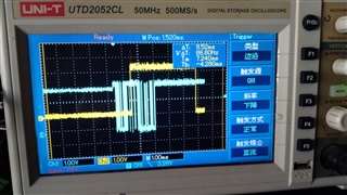
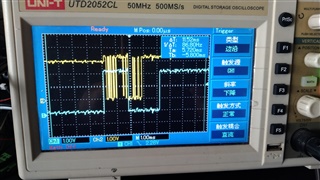
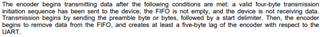
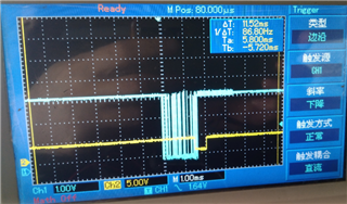
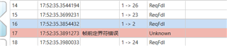
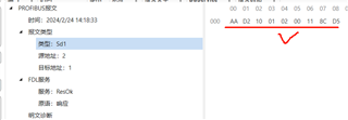
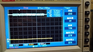
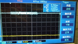
Now I can receive frame from PROFIBUS PA bus correctly, I can check it in my MCU as UART_OUT is connected to the RX pin of my MCU.
But I can't transmit frame to the PROFIBUS PA bus through DAC8740H UART_IN.
Detail description:
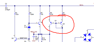
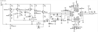
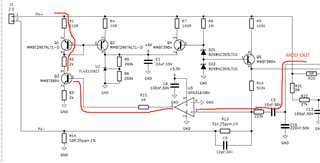
1. My schematic is based on DAC8740H_PAFF.SchDoc offered by TI E2E website.
2. To avoid PROFIBUS PA master unexpected interfere, I only connected PA+ and PA- to 30V and GND from a DC source.
3. Duplex pin is set to low level by MCU, before RST(pin5) is set to high. So half-duplex is used!
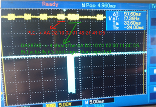
4. what's the deep of transmit FIFO of DAC8740H? 16 bytes or others?Could I transmit 16 bytes continuously once to UART_IN of DAC8740H firstly?
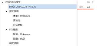
5. I see in the datasheet, a start delimiter is need before the user data stream, is start delimiter must be 0x2D or there is some rule to define?
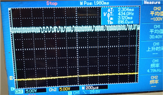
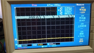
6. I first transmit frame stream "EA 8B 00 AE FF FF FF FF 2D 10 00 02 00 35 30" to UART_IN of DAC8740H,
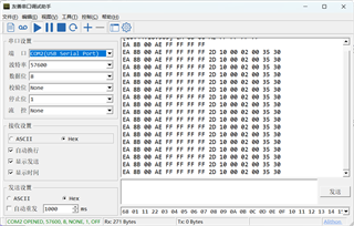
in which