This thread has been locked.

If you have a related question, please click the "Ask a related question" button in the top right corner. The newly created question will be automatically linked to this question.

DAC8740H: Hart communication work in SINK mode but failed in 4-20mA Source and Isolation current output Mode

Part Number: DAC8740H
Other Parts Discussed in Thread: DAC161S997,

Dear Team,

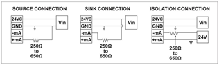
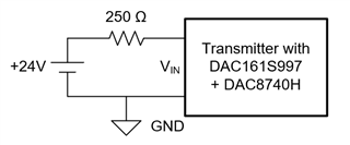
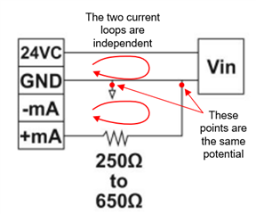
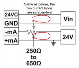
We have designed the current output circuit using the DAC161S997 IC and the DAC8740 HART IC. For detailed design information, please refer to the attached document. According to our design, the HART communicator connects with our system when it is operating in SINK mode. However, when we switch to Source mode or Isolation Mode, the HART IC does not send digital data to the MCU. We are using a 500-ohm resistor as the load. This system functions as a 3-wire system in both sink and source modes, and as a 4-wire system in Isolation mode. Kindly review the details and update me if there are any mistakes.

4-20mA and Hart communication.pdf

  • Hi,

    I'm not sure what you mean by sink mode, source mode, and isolation mode. I can see the schematic, so can you describe the connections that you would make for these three modes? Generally the DAC161S997 was designed as a transmitter and is meant for a two-wire system.

    One thing that often comes up with the DAC161S997 is that the COM and OUT pins need to be independent from each other because it controls the current of the loop. If the two are connected, the control is broken, and the current through the loop is minimized to the amount of current required for the circuit. I'm not sure if that's what's happening in your system, but it does often come up.

    Joseph Wu

  • Hi joseph,

    Currently, my 4-20mA output is functioning properly, but my HART communication is not working. According to the previously attached schematic, could you please confirm whether the ground (DGND) of the DAC8740 and the GNDI of the DAC161S997 should be the same? If they are different, will HART still work?

  • Hi,


    For the schematic, if the DAC8740H ground and the DAC161S997 ground were connected, then I think the circuit should work. However, if you have the grounds isolated, I think the circuit should work too. When the board is set up for Source and Isolation modes, what voltages do you see from TP1 to TP2? What are you connected to in those modes?

    Where is HART-MOD-IN connected? It is only shown on the schematic going out of the DAC161S997 through the C2 capacitor. In the Source and Isolation modes, do you use some sort of load resistor?

    You should also use and oscilloscope to look at the signals on the board. When testing the HART in the Source and Isolation modes can you see the HART signal at HART-MOD-IN and do you see it at TP4? I just want to make sure the signals even being transmitted.


    Joseph Wu

  • Hi Joseph,

    Thank you for your guidance. Please find attached the waveform signals. I have attached the SINK mode waveform (which is communicating properly) and the SOURCE mode waveform (which is not communicating) for comparison. I have observed that when we replaced the 250-ohm resistor with an inductor L1, the source communication also started working. However, the total load resistor should be 500 ohms (external resistor) + 250 ohms(L1) = 750 ohms, which I believe is not an ideal solution.

    Hart signal detail.pdf

  • Rohit,


    I'm going to need a little more time with this one. The way that you have the device setup for Source, Sink, and Isolation aren't the way I normally see this device used. Just so that others can see this easily, this is how you have the connections set up as you described in the PDF:

    Generally, I see this device set up as a remote transmitter, where the device is in series with the resistive load:

    In this transmitter, the current is modulated to create the HART signal, so the voltage at the top of VIN modulates and the DAC8740H is able to sense the signal with MOD_IN.

    Again, give me a little more time to review your circuit.


    Joseph Wu

  • Hi Joseph,

    Thanks for reply. please correct if any any design mistakes.

  • Hi,


    I've been looking over your pdfs, and I'm not sure your connections to this circuit are how they are drawn to be. Even for the sink diagram, I think it is a little off from what I expect. Let me use your diagrams to show what I see wrong in your schematics.

    First, above is your Source connection. The VIN is connected to the 24V supply to GND. Additionally, there is another lead labeled +mA. I assume this is a source that outputs current. For the board labeled VIN, this device controls the loop current coming from from the supply. However, the load resistance is attached to ground. If VIN modulates the loop current, the resistance never sees that modulated current. The +mA source and the ground make a separate loop. There would be modulated voltage to sense off of the resistor.

    Second, you have the same problem with the Isolation connection. There's no connection between the two loops. If you modulate the current through VIN, there's no way to sense that current modulation.

    For the Sink connection, there's also a problem with the connection. The load resistance and the VIN create independent loops, you wouldn't be able to see the current modulation on the load resistance. It might work if the load resistor is tied to the supply and ground, and there is a series resistance. In that case, the load resistor top voltage still gets modulated because it's at the bottom of a series resistance that sees the modulation.

    Can you be a little more descriptive with your setups? It might help to know what -mA and +mA really are. Are they just current sources that sink and source a specific amount of current?

    In the end, the modulation of the current in the device must be pulled across the load resistor to be seen. In each of the setups, I would have expected a series connection between the resistor and the device.


    Joseph Wu

  • Hi Joseph,

    Thanks for clarification,

    We are utilizing either 3-wire (sink OR source) or 4-wire (isolation) 4-20mA current output connections. We are connecting the HART communicator at Connector P1 as displayed in the schematic diagram. The +mA and -mA serve as the only current sources, which we select using switches SW1 and SW2. Please refer to the output section table chart in the schematic for further details.

    Please confirm me about the optimal location for connecting Resistor R4 if I intend to incorporate a 4-20mA current output monitor circuit for feedback in this design. Should I connect it upstream, before D1, or after D3 (as per the PDF)? Which location would provide the best coverage for maximum diagnostic capability?

    4-20mA and Hart communication (3).pdf

  • Rohit,


    It shouldn't matter if the resistor is before D1 or after D3. The board would generally work because the sinusoid would be seen regardless. However, I still don't fundamentally understand your connections to this device.

    The DAC161S997 is typically used for two-wire transmitters. It is not meant for 3-wire transmitter topologies. The DAC161S997 is used to set a current through the loop. If some other source (like your current source connections), try to drive a current against the current control in the DAC161S997, I think the voltage across the loop would collapse.

    For your setup, you can set up the device with source mode (which you mentioned isn't working) and measure the voltage across the TP1 and TP2, and measure the current across R4 to see what you get. You can also measure across R2/R3 to check that current, and record the voltage around the schematic (BASE, TP3, OUT, 3.3V1).


    Joseph Wu