DAC43401-Q1: Want 0 to 1.8 v square wave output,

Part Number: DAC43401-Q1
Other Parts Discussed in Thread: DAC53701, DAC53701EVM

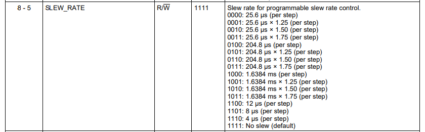
GENERAL_CONFIG Register Field Descriptions

Want 0~1.8v square wave output, need to explain I2C setting method

  • Hi Jaeseong,

    The square wave frequency is defined as:

    SLEW_RATE is defined as:

  • How do you set initial register values?

  • Hi Jaeseong,

    The datasheet helps to describe I2C communication protocol on starting on page 27. Additionally, we will need to know if you are using the internal reference or the VDD as a reference. I will assume here you are using a 5V VDD reference.

    To set the output of the square wave, write to these specific registers:

    Register 0x25, DAC_MARGIN_HIGH. This is where you will set your 1.8V output. With 5V VDD, this is roughly data 0x5C, or 92. For this register, you would write 0x0170. 

    Register 0x26, DAC_MARGIN_LOW. This should remain 0x0000.

    Next, you should turn on the DAC. Register 0xD1, GENERAL_CONFIG. This register has the Square wave command, the DAC power on command, and the Slew rate setting. In this register, write 0xC000. This will give a square wave will a frequency of around 19kHz. 

    Finally, you write to the trigger register, 0xD3. Write 0x0208 to start the function generator. 

    Rewrite the registers until you get your ideal output range and frequency. To save the data to the NVM, write 0x0218 code to register 0xD3.

    Let me know if you have any other questions.

    Thanks,
    Erin

  • If you use 0xD3 as 0x0208 as you told me, it resets everything, but I think that's not right. Please check again for the address values.

  • Hi Jaesong,

    In register D3, write 0x0108. This should start the function generator. 

    When you are ready to write NVM, write 0x0118.

    Thanks,
    Erin

  • Hi Erin,

    I'm setting the DAC device as you said. (please check below)

    ==========================================

    root@sa6155:~# yi2cset -f 9 0x48 0x25 0x0170 w
    options(w)
    root@sa6155:~# yi2cset -f 9 0x48 0x26 0x0000 w
    options(w)
    root@sa6155:~# yi2cset -f 9 0x48 0xD1 0xC000 w
    options(w)
    root@sa6155:~# yi2cset -f 9 0x48 0xD3 0x0108 w
    options(w)
    root@sa6155:~# yi2cset -f 9 0x48 0xD3 0x0118 w
    options(w)

    ==========================================

    root@sa6155:~# yi2cget -f 9 0x47 0xD0 w

    options(w)
    0x1014

    I'm looking at logic analyzer wave, it remains LOW and there's no change when I write that reg & values.

    But I write (the first guide you told us)  D3 0x0208 the wave goes up HIGH.

    Can you check again?

  • I run the evaluation tool kit(DAC53701EVM-GUI) and there's an error like below.

    Can you fix it?

    Thanks.

    =============================================================================================

    Possible reason(s):

    LabVIEW: (Hex 0x3EB) The VI is not executable. This error may occur because the VI is either broken or contains a subVI that LabVIEW cannot locate. Select File>>Open to open the VI and verify that you can run it.

    VI Path: C:\Program Files (x86)\Texas Instruments\DAC53701EVM\DAC53701EVM.exe\DAC53701\SW\SRC\Main.vi

  • Erin is reviewing this now.

  • Hello,

    Run the GUI in Administrator mode and let me know if that error still appears.

    I'm reviewing the I2C writing commands and will let you know if I find out anything. When you do your I2C programming, can you read back from the registers you program to make sure the device is registering your writes.

    Thanks,
    Erin

  • Hello, 

    Please try installing the GUI by running the exe in administrator mode. Can you also verify that the labview runtime engine was installed (this should install as part of the GUI). 

    Can you share an oscilloscope screenshot of the five I2C commands you are sending? Have you been able to control the DAC output with a static voltage using the DAC DATA register? 

    Best,

    Katlynne Jones