ADS127L18: How many devices can be daisy-chained?

Part Number: ADS127L18

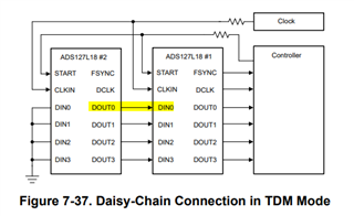
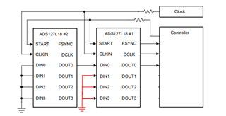
It is difficult to me from the datasheet to find out how many devices can be daisy-chained.

I want to use a one-bit stream to an FPGA.

I want to daisy-chain 8 devices for 64 channels.

The "tc (DCLK) period DOUT to DIN daisy-chain connection " is spec'd as 29.8 nS .

Does it mean I need a tc (DCLK) period of 8x 29.8 = 238.4 nS  (4.19 MHz)?

  • Hello Ton,

    The maximum number of channels is dependent on a number of settings and configurations.  tc(DLCK) minimum is 29.8ns, which limits the maximum data clock (DCLK) frequency to 33.557MHz.  This is also the maximum clock frequency for the ADC clock.  This is necessary to meet the setup and hold time requirements for DIN0 accounting for the propagation delay on DOUT0.

    Below is my attempt to combine all of these settings into a single equation to calculate the maximum number of L18 devices in daisy-chain, N, where the total number of channels will then be 8*N.

    N=(CLK_DIV*OSR*TDM)/(DCLK_DIV*Packet_Size*4), where the calculated value of N is rounded down to the nearest integer.

    CLK_DIV is the clock division setting for the ADC data rate, where CLK_DIV can equal 1,2,3,4, or 8.

    OSR is the oversampling ratio setting of the digital filter; refer to tables 6-1 through 6-5 for available OSR settings and resulting data rates.

    TDM is the number of DOUT pins used; 1,2, or 4 are available in daisy-chain operation.

    DCLK_DIV is the data clock division setting for the output data rate, where DCLK_DIV can equal 1,2,4, or 8.

    Packet_Size is the number of bits per channel per frame, 16, 24, 32 or 40, depending on 16b or 24b data, optional Status byte and optional CRC byte.

    In your specific use case, you want to daisy chain 8x ADS127L18 devices (N=8) for a total of 64 channels, using only the DOUT0 pin (TDM=1).  Assuming you do not enable the CRC or STATUS bytes, then your packet size for each channel will be 24 to support 24b readings.  I will also assume DLCK_DIV=2 and CLK_DIV=3 to support the highest possible data rate.

    Based on these assumptions the minimum supported OSR value (maximum data rate) will be:

    8 = (3*OSR*1)/(2*24*4)

    OSRmin = 512

    In HIGH-speed mode and fCLKIN=65.536MHz, fCLK=fCLKIN/CLK_DIV=21.845MHz and fDCLK=fCLKIN/DCLK_DIV=32.768MHz, this will result in a maximum possible data rate per channel of 21.3ksps.

    Regards,
    Keith Nicholas
    Precision ADC Applications

  • Thanks for quick reply Keith!

    I have to digest this information before it all is clear. You schematic shows 4x DOUT going to the controller, does that mean I cannot get all data over ONE line? I would use the converter in Wideband with 24 bit data (no status and CRC) at an output sample rate of max. 8192 Hz.

  • Hello Ton,

    You only need ONE line, DOUT0.  I redrew the schematic showing 2 of 8 total ADS127L18s to hopefully make this more clear.

    Since your maximum sample rate is 8192Hz, which is less than the maximum sample rate supported in this configuration of 21300Hz, this will work well.  I would suggest using an OSR setting of 1024, which will further improve SNR (effective resolution).  With this configuration, your main clock frequency, CLKIN, for all ADS127L18's would need to be adjusted to 8192*1024*2*3 = 50331648Hz. 

    Using a standard value clock frequency of 50MHz with these settings would result in a data rate for each channel of 8138Hz, slightly below your target, but you can custom order oscillators, or use a programmable PLL, to generate the exact 50.331648MHz frequency needed to achieve your desired data rate.

    Regards,
    Keith

  • Thank you Keith!

    I start working on my schematics now.

    So far, my questions are resolved.