This thread has been locked.

If you have a related question, please click the "Ask a related question" button in the top right corner. The newly created question will be automatically linked to this question.

ADS124S08EVM: ADS124S08 ADC Incorrect Signal Reading with 4.6V Input

Part Number: ADS124S08EVM
Other Parts Discussed in Thread: ADS124S08

Hello Texas Instruments Support Team,

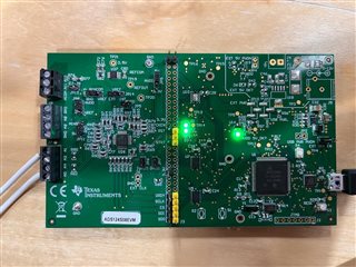
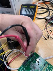
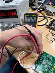
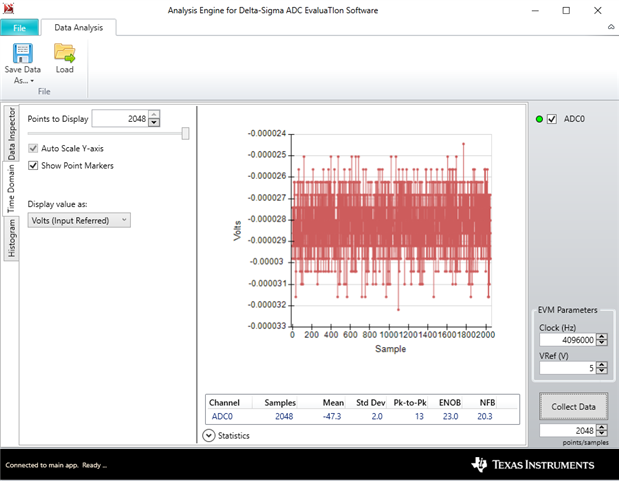
I am currently working with the ADS124S08EVM and have encountered an unexpected behavior during signal readout. I connected a 4.5V battery across input pairs AN0(+) and AN1(-), as well as AN10 and ANCOMMON, for differential measurement.

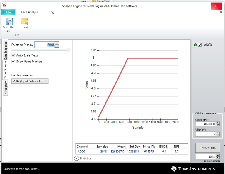
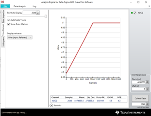
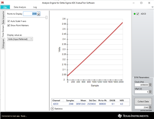
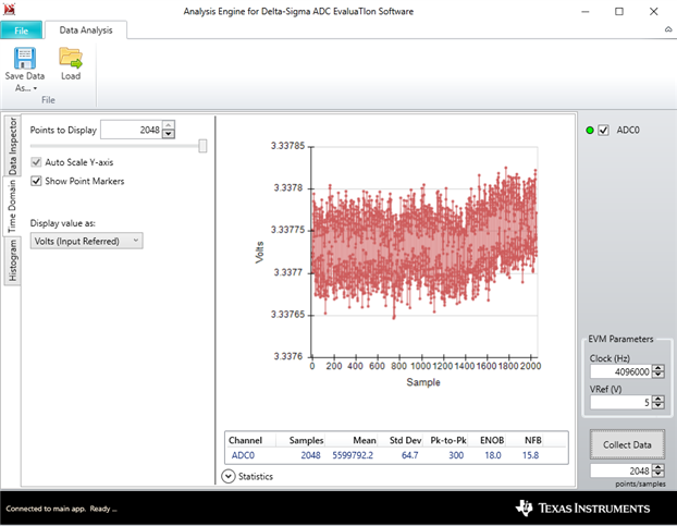
Using the TI evaluation software, the readout initially displays the correct voltage of 4.5V. However, after a certain number of samples, the readings begin to ramp up linearly and eventually saturate at 5V, the VREF I set in the software. I’ve attached a screenshot from the evaluation software showing the observed behavior.

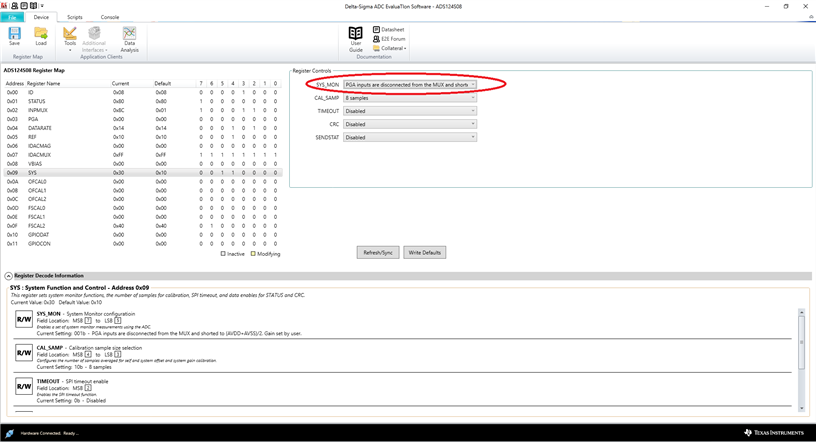
Configurations are default set, only changed the input and sample rate (for tests)

• VREF: 5V
• Clock: 4096000 Hz
• Input Channels: AN0(+) with AN1(-) and AN10 with ANCOMMON

Could you please assist me in understanding the potential causes of this issue? Are there any steps I should follow to resolve this?

Warm regards,

Artur

  • Hi Artur,

    You changed VREF on the Data Analysis page, but the default configuration may not be correct.  Can you send me a screen shot of the register map page?  The REF register should be set to REFP0,REFN0 for REFSEL input.  Also, can you verify that the jumper settings for JP8 is set to AVDD and JP11 set to AGND?

    If you connect to AIN10 and AINCOM, this is a voltage divider so for sure you should not see a full-scale reading.  Do you see the exact same thing in each for the data analysis results for both connection cases, or does it appear differently?

    Best regards,

    Bob B

  • Hi Bob,

    Attached is a picture of my development board, which is set with all jumpers in the default position as outlined in the manual:


    Furthermore, the registers are configured as follows, in the default mode of the SigmaDelta program.
    One peculiar observation is that when reading from the AI0(+) and AI1(-) channel, the value remains pegged at 5V, as shown in the image below:

    However, when I switched AI1 to AICOM, the result was as previously described: the initial reading shows the correct voltage, but subsequent readings ramp up and saturate at 5V.

    I conducted several measurements with single samples to observe the behavior, and it appears that with each measurement the readout incrementally increases until saturation.

    My last observation that I fit some pin header to connect an extra mcu to connect with the ADS124S08. 

  • Hi Artur,

    For the input voltage for AIN0/AIN1 the voltage is actually showing as -5V, so it is not clear about the voltage source connection.  Can you measure the voltage with an external voltmeter from each input separately to analog ground ( terminal marked GND)? Please measure the voltages and post them.  One consideration here is AIN0 has a 1k pulldown resistor for RTD biasing.  So perhaps this R70 resistor is affecting the measurement in some way.

    For the AIN0/AINCOM you still have the pulldown resistor in the circuit path.  It is not clear why it is floating to positive full-scale other than there are a number of capacitors that may be charging.  Again it would be helpful to measure with a voltage meter the AIN0 input to GND.  Please post the results.

    My suggestion would be to use inputs that are not connected to biasing resistors.  Instead of AIN0/AIN1 you may want to use the pairs such as AIN2/AIN4 (or AIN8/AIN9) for differential input.  For the single-ended input, there really isn't a specific use case connection.  Again I would try an input not connected to a resistor to GND, perhaps AIN8, or AIN2 for the + connection.

    Best regards,

    Bob B

  • Thank you for your suggestions. I have now measured the voltage at the AIN0 terminal and GND with an external voltmeter, and the values are consistent with the input using a DC power source.

    But the result expected was that we should be seeing a constant value, not a ramp. What could be the reason for the ADC to read the correct value on the first sample and then have subsequent samples increasing to full scale? Could this possibly be a hardware issue?

    I have also conducted measurements using AIN8+ with ACOM and AIN8+ with AIN9-, and the results were the same, exhibiting the same ramping behavior.

    Also, I'm trying to read a unipolar measurement.

  • Hi Artur,

    I asked for posting the voltages you measured.  And now it is unclear if you are actually using a battery or some other voltage source.  If the voltage source is from an AC powered supply, the grounds may be an issue.  I have seen voltage sources as much as 40V different between the EVM and the AC power supply.  Please give me detailed information regarding your source and the voltages measured with respect to board GND.

    Best regards,

    Bob B

  • Hello Bob, sorry for misunderstanding.
    On my first examples I was using a battery with 4.5V and now I'm using an external dc power supply to achieve different voltage values.
    First Scenario using a battery, now on AIN8+ and AICOM;
      

    And second scenario using a external power supply, now on AIN8+ and AICOM;

  • Hi Artur,

    This is very unusual.  Can you try turning on and using the internal reference with the 2V input to see if there is any change in behavior?  If you see something similar then it is possible the ADC was damaged.

    Best regards,

    Bob B

  • Hi Bob,

    Apologies for the delay in my response.

    Today, I conducted several tests, including using the internal reference; however, the outcome remained unchanged. Interestingly, when I switched to Single Shot measurement and modified the register to "Collect Data," the software did not respond. Consequently, I wrote a script that sends the Start Conversion command, followed by the Read Data (RData) command, and finally the Stop Conversion command. This approach yielded correct results. I repeated this process several times with varying voltages, and it functioned correctly every time.

    However, my project requires the use of Continuous Mode. When running the script in this mode, the ADC returned full-scale data (7F FFFF). Could you provide guidance on any additional steps needed to ensure Continuous Mode operates correctly?

    Additionally, I ran the SBAC301 unit_test code on my external processor, and the chip passed all tests. Is there another diagnostic tool or code I can use to confirm the integrity of the EVM board?

    Your insights would be greatly appreciated.

    Thank you so much.

  • Another intriguing observation from today's testing involved using my external CPU for control. When reading in DIRECT mode, out of 100 readout commands, the first 75 provided accurate data, but subsequently, the ADC began delivering incorrect values.

  • Hi Artur,

    One specific question, is D2 on continually or is it off when not collecting data?  D2 is designed to toggle about once a second, but only when collecting data. 

    There are a couple of other simple tests that can narrow this down as to whether or not the issue is with the ADC or external source connections.  First try applying an internal short.  This can be done using the system monitor which is in SYS register settings.

    Here is my result using the internal short with the 5V AVDD as the reference.

    There are also other combinations that can be tried like internal temperature sensor, (AVDD-AVSS)/4, DVDD/4, etc..

    If those internal measurement values appear to be ok, then you can apply an external voltage measurement.  Instead of an external source I used the 3.3V from the EVM as input to AIN8, and then measured AIN8/AINCOM (using the appropriate mux input settings).  Here you need to remember to return the SYS_MON settings back to Disabled first.

    Here is my result:

    So here you can see that I'm getting good results using very simple tests with no external sources.

    You have modified your board for connecting to an external processor.  Did the EVM work as expected with the EVM GUI prior to these changes?  

    Using the external processor, how are you powering the EVM?  Did you ever accidently apply 5V to the DVDD?

    If after running the above tests you still are seeing issues, then I can only surmise that the ADS124S08 on the EVM became damaged in some way.  This could have happened either when connecting your external processor or by accidentally applying a voltage outside of the input range of the ADC and thus exceeding the absolute maximum ratings for the ADS124S08.

    Best regards,

    Bob B