ADS1298: Simulation of ADS1298

Part Number: ADS1298
Other Parts Discussed in Thread: OPA350, TINA-TI

Tool/software:

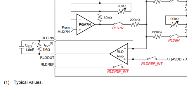
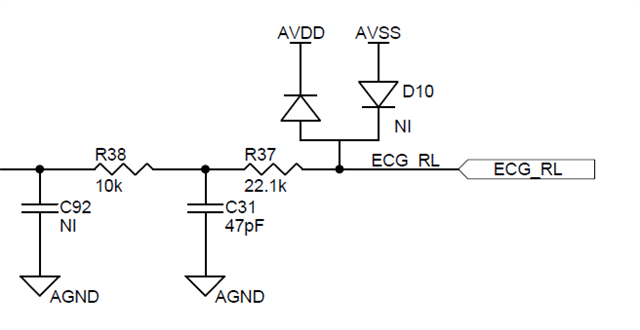
We are working on an ECG project using ADS1298 from Texas Instruments as our analog front end module. So before getting the design done practically, we thought of testing the connections and also about passive resistors and capacitors values by simulating it in a virtual environment, In TINA-Texas simulation tool we didn't found ADS1298 for simulation. i request your help in finding some appropriate library to load ADS1298 spice model into TINA for simulation purpose or some other simulation tools that has ADS1298 spice model in it.  

  • Hello Varun,

    Thank you for your interest in our ADS1298. Unfortunately, we do not offer a PSpice or TINA-TI model for our ADS1298 since it is a complex device with an input PGA, RLD feedback amplifier, lead-off detection current sources and comparators, etc. Is there a specific portion of the device you are interested in modeling? For the PGA stage, the OPA350 has similar input impedance and bandwidth characteristics, which could be used as a first-order approximation of the input stage in the ADS1298.

    Regards,

    Ryan 

  • Hello Ryan,

    Firstly, I would Thank you for giving me the unknown insights about ADS1298 and OPA350 both have similar input impedance and bandwidth characteristics.

    Our main intention was to find out the right value of passive components like capacitors and resistor that we place at the VDDA pins, so that the ADS1298 powers up with no issues and works.

    If you can help us in providing the internal block diagram components of ADS1298, we can try to build an approximation of ADS1298, and try simulating it.

  • Hello Varun,

    The only block diagram details I can provide are included in the device data sheet (section 9.2). For power supply sequencing and recommended decoupling, please refer to Sections 10.1.1 and 11. The EVM User Guide also has examples of decoupling capacitor values and layout.

    Regards,

    Ryan

  • Hello Ryan,

    Can I get the information about the RLD Amp, (its characteristics), because we were not sure about patient protection. In the EVM User manual, The RLDOUT pin is directly connected to patient electrode. But it seems a bit risky to connect it directly to the patient without knowing about the bias current and output impedance of the amplifier.

    And also please, suggest us in designing circuit for protecting patient from any high currents from RLD Amp.

  • Hello Varun,

    The RLD amplifier short-circuit current is less than 1mA as listed in the Electrical Characteristics table. In the User Guide, we show the same second-order LPF between the RLDOUT pin and the electrode connection as used for the other ECG input electrodes:

    Regards,

    Ryan