This thread has been locked.
If you have a related question, please click the "Ask a related question" button in the top right corner. The newly created question will be automatically linked to this question.
Tool/software:
Hi team,
I am working the project of 8 channel DAQ for using the ADS1278.
Configure the high speed mode for sampling at 65536SPS_FCLK_16.777MHZ.
Next enable the 4 channel and Using the spi protocol for read the ADC data.
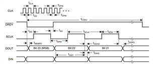
SPI read using 16 bit mode.It's take 6 cycle(6 x 16) = 96 clock pulse_4 channel x 24 bit = 96 bit .ADC reading by SPI _TDM Mode(Dynamic Position Data).
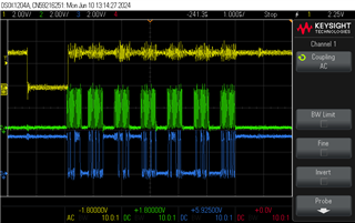
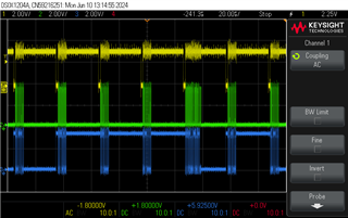
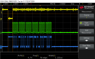
1st and 3rd channel data output correctly as per the input signal
But 2nd and 4th Channel output is aliasing with some noise,But input for all the 4 channel is given from one same source.
How to solve the issue.!
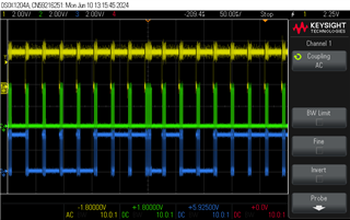
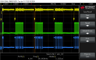
And ,I will read the 2nd,3rd and 4th.In that time 2nd and 4th channel is correct .3rd channle aliasing with some noise.
SPI reading settup
for(data = 0; data < 6; data++)
{
SSIDataPut(SSI0_BASE, 0);
SSIDataGet(SSI0_BASE, &SPI_Data[data]);
HF_msg[i++] = (SPI_Data[data] >> 8) & 0xFF;
HF_msg[i++] = SPI_Data[data];
}
Thanks and Regards,
Aravind
Hello Aravind,
It appears that you may not be reading the data fast enough from the ADC before the next conversion result.
Data needs to be read after the falling edge of /DRDY, and the data read must complete at least 1 clock period before the next /DRDY falling edge.
Regards,
Keith Nicholas
Precision ADC Applications
Hi keith,
Thank you for the support.
Read the data form ADC through the SPI
ADC sampling speed for FCLK is 15 MHz=15000000/256 = 58593.75 SPS
SPI data rate is 30 MHz and 16 bit mode
Above the give SPI FORMAT TIMING we are reading the data
Yellow - DRDY
Green - SCLK
Blue - Data(MISO)
That time we given 112 clock pulse.
In 112 clock plus -First 16 Clock pulse Not provide the valide Sensor data only Last 96 clock pulse provide the 1 - 4 channel data.
Thanks and Regards,
ARAVIND
Hello Aravind,
SCLK frequency must be equal to or less than CLK frequency, other your data will be corrupted.
With FCLK=15MHz, SCLK must be less than or equal to 15MHz.
In your case, setting f-SCLK=f-CLK or f-SCLK=1/2*f-CLK would be ideal.
Regards,
Keith
Hi keith,
Thank you for the support.
Read the data from SPI Speed is 10MHZ.
Sampling speed is 20MHZ .
all the four channel is Not provide the valide Sensor data.
Yellow - DRDY
Green - SCLK
Blue - Data(MISO)
What we can do?
Thanks and regards,
Aravind.SR
Hello Aravind,
Please connect a steady DC voltage for debug purposes. For example, AINP=3.5V and AINN=1.5V. This should readback as a positive 2V differential voltage, assuming Vref=2.5V. The approximate code in this case should be 0x666666h.
Also, please show include a scope plot similar to the ones above, but zoomed in to show the first 32 SLCK's (first 2 16b transfers). This will verify that the ADC is operating correctly and for a known DC input level.
Regards,
Keith