Tool/software:
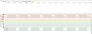
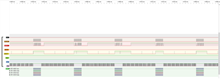
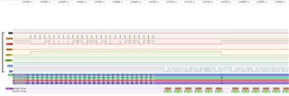
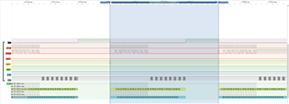
Use ADS199FE-PDK to connect to the development version of STM32F4052 through SPI. The mcu spi baud rate is set to 2M, CPOL=LOW, CPHA=2 Edge. I turn on the eight-channel test signal input and use a logic analyzer to find the value of each channel. The difference is not big, as shown in Figure 1, but after each SPI transmission, using UART for Bluetooth transmission, the SPI value will become very strange, as shown in Figure 2. Is this normal?
And how can I check that the SPI result is correct? Thank you.
Figure 1 Logic analyzer results
Fig1.
Figure 2 Logic analyzer results
Fig2.
/* USER CODE BEGIN Header */
/**
  ******************************************************************************
  * @file           : main.c
  * @brief          : Main program body
  ******************************************************************************
  * @attention
  *
  * Copyright (c) 2024 STMicroelectronics.
  * All rights reserved.
  *
  * This software is licensed under terms that can be found in the LICENSE file
  * in the root directory of this software component.
  * If no LICENSE file comes with this software, it is provided AS-IS.
  *
  ******************************************************************************
  */
/* USER CODE END Header */
/* Includes ------------------------------------------------------------------*/
#include "main.h"
#include "stdio.h"
/* Private includes ----------------------------------------------------------*/
/* USER CODE BEGIN Includes */

/* USER CODE END Includes */

/* Private typedef -----------------------------------------------------------*/
/* USER CODE BEGIN PTD */

/* USER CODE END PTD */

/* Private define ------------------------------------------------------------*/
/* USER CODE BEGIN PD */

/* USER CODE END PD */

/* Private macro -------------------------------------------------------------*/
/* USER CODE BEGIN PM */

/* USER CODE END PM */

/* Private variables ---------------------------------------------------------*/
SPI_HandleTypeDef hspi1;

UART_HandleTypeDef huart1;

/* USER CODE BEGIN PV */

/* USER CODE END PV */

/* Private function prototypes -----------------------------------------------*/
void SystemClock_Config(void);
static void MX_GPIO_Init(void);
static void MX_SPI1_Init(void);
static void MX_USART1_UART_Init(void);
/* USER CODE BEGIN PFP */

/* USER CODE END PFP */

/* Private user code ---------------------------------------------------------*/
/* USER CODE BEGIN 0 */

/* USER CODE END 0 */

/**
  * @brief  The application entry point.
  * @retval int
  */
int main(void)
{

  HAL_Init();


  SystemClock_Config();


  MX_GPIO_Init();
  MX_SPI1_Init();
  MX_USART1_UART_Init();

  /* USER CODE BEGIN 2 */
  //int received_byte; // 定義接收字節變量

  HAL_GPIO_WritePin(GPIOC, reset_Pin, GPIO_PIN_SET);

  uint8_t RESET = 0x06; // 復位ADS1299命令
  HAL_Delay(1000);
  HAL_SPI_Transmit(&hspi1, (uint8_t*)&RESET, 1, 0x1000);
  HAL_Delay(1000);

  uint8_t ID = 0x00;
    //uint8_t為一個char
  uint8_t SDATAC = 0x11; // stop read data
  uint8_t RDATAC = 0x10; // 讀取連續數據


  uint8_t START = 0x08; // 啟動命令
    // uint8_t STOP = 0x0a; // 停止命令(未使用)
    // uint8_t WAKEUP = 0x02; // 喚醒命令(未使用)
    // uint8_t STANDBY = 0X04; // 待機命令(未使用)

  uint8_t test = 0x00; // 測試變量


    uint8_t CONFIG1 = 0x01; // 配置寄存器1
    uint8_t CONFIG2 = 0x02; // 配置寄存器2
    uint8_t CONFIG3 = 0x03; // 配置寄存器3

    uint8_t CH1SET = 0x05; // 設置通道1
    uint8_t CH2SET = 0x06; // 設置通道2
    uint8_t CH3SET = 0x07; // 設置通道3
    uint8_t CH4SET = 0x08; // 設置通道4
    uint8_t CH5SET = 0x09; // 設置通道5
    uint8_t CH6SET = 0x0A; // 設置通道6
    uint8_t CH7SET = 0x0B; // 設置通道7
    uint8_t CH8SET = 0x0C; // 設置通道8

//    uint8_t BIAS_SENSP = 0x0D; // 設置Bias Drive Positive Derivation Register
//    uint8_t BIAS_SENSN = 0x0E; // 設置Bias Drive Negative Derivation Register
//    uint8_t LOFF_SENSP = 0x0F; // 設置Positive Signal Lead-Off Detection Register
//    uint8_t LOFF_SENSN = 0x10; // 設置Negative Signal Lead-Off Detection Register
//    uint8_t LOFF_FLIP	 = 0x11; // 設置Lead-Off Flip Register
//    uint8_t LOFF_STATP = 0x12;
//    uint8_t LOFF_STATN = 0X13;
//
//    uint8_t GPIO	= 0x14; // 設置GPIO
//    uint8_t MISC1 = 0x15; // 設置MISC1
//    uint8_t MISC2 = 0x16; // 設置MISC2
//    uint8_t CONFIG4 = 0x17; // 設置寄存器4

    uint8_t received_Byte; // 定義接收字節變量
    uint32_t dataPacket = 0;
    uint32_t output[9] = {0};
    int counter = 0;
    int length;

    uint32_t data_test = 0x7FFFFF; // 測試數據
    uint32_t data_check = 0xFFFFFF; // 檢查數據

    uint32_t result[4]={0}; // 定義結果變量
    uint32_t result_before; // 定義先前結果變量
//    int average_result_massiv[10] = {0}; // 定義平均結果數組
//    int average_result; // 定義平均結果變量
//
//    uint32_t noise_massive[100] = {0}; // 定義噪聲數組
//    uint32_t final_noise_massive[100] = {0}; // 定義最終噪聲數組
//    uint32_t summa_noise; // 定義噪聲總和變量
    int zad = 8; // 定義任務變量
//    int i_count = 0; // 定義計數器變量
//    int average_count = 0; // 定義平均計數器變量
//    int pcktcnter = 0;

    uint8_t out1 = 0;

    uint8_t new_data_flag = 0;
    // 發送命令函數
     void send_command(uint8_t cmd)
     {

     		 HAL_GPIO_WritePin(GPIOA, CS_Pin, GPIO_PIN_RESET);// 拉低CS引腳選擇芯片
     		 HAL_SPI_Transmit(&hspi1, (uint8_t*)&cmd,1, 0x1000);// 通過SPI發送命令,HAL_SPI_Transmit(SPI_HandleTypeDef *hspi, uint8_t *pData, uint16_t Size, uint32_t Timeout)
     		 HAL_GPIO_WritePin(GPIOA, CS_Pin, GPIO_PIN_SET);// 拉高CS引腳釋放芯片
     }

     void send_data_by_uart(uint32_t outputdata)
     {

    	 	 	 //HAL_UART_Transmit(&huart1, &outputdata, sizeof(outputdata), 10); // Transmit the entire buffer
    	 	 	 //outputdata is a (4x24bit) array with 4 corresponding to 4 channels

    	 	 	// step 1 - convert dataset
    	 	 	char buffer = {0};
    	     	char buffer1[6] = {0};

    	 	 	sprintf(buffer1, "%06x",  outputdata);

    	 	 	for (int i=0;i<6;i++)
    	 	 	{
    	 	 		if (buffer1[i]!= '\0')
    	 	 		{
    	 	 			   buffer = buffer1[i];
    	 	 			   HAL_UART_Transmit(&huart1, &buffer, 1, 10); //original timeout = 1000
    	 	 		}
    	 	 		else
    	 	 		{
    	 	 			continue;
    	 	 		}
    	 	 	}//end of for (int i=0;i<6;i++)

    	 	 	if (counter == 7) // if send_data_by_uart has run 4 times then it means all data channels have been transmitted
    	 	 	{
					buffer = '\n'; //send "\n" after all channels have been sent to BLE
					HAL_UART_Transmit(&huart1, &buffer, 1, 10);
					counter = 0;

    	 	 	}// end of if(counter == 3)

				else
				{
					counter += 1;
				}


     }// end of send_data_by_uart


 	// 寫入字節函數
 void write_byte(uint8_t reg_addr, uint8_t val_hex)
 {
 		HAL_GPIO_WritePin(GPIOA, CS_Pin, GPIO_PIN_RESET);// 拉低CS引腳電壓,選擇芯片使其動作
 		uint8_t adress = 0x40|reg_addr; // 定義寄存器地址
 		HAL_SPI_Transmit(&hspi1, (uint8_t*)&adress, 1, 0x1000);// 發送寄存器地址
 		HAL_SPI_Transmit(&hspi1, (uint8_t*)&test, 1, 0x1000);// 發送測試數據
 		HAL_SPI_Transmit(&hspi1, (uint8_t*)&val_hex, 1, 0x1000);// 發送要寫入的數據
 		HAL_GPIO_WritePin(GPIOA, CS_Pin, GPIO_PIN_SET);
 }

 	// 讀取字節函數
 uint8_t read_byte(uint8_t reg_addr)
 {
 		uint8_t out; // 定義輸出字節變量
 		HAL_GPIO_WritePin(GPIOA, CS_Pin, GPIO_PIN_RESET);// 拉低CS引腳電壓,選擇芯片使其動作
 		uint8_t adress = 0x20 | reg_addr ;  // 定義寄存器地址
 		HAL_SPI_Transmit(&hspi1, (uint8_t*) &adress, 1 ,0x1000);// 發送寄存器地址
// 		HAL_SPI_Transmit(&hspi1, (uint8_t*)&test, 1, 0x1000);// 發送測試數據
// 		HAL_SPI_Receive(&hspi1, (uint8_t*)&out,1, 0x1000);
 		HAL_SPI_TransmitReceive(&hspi1,(uint8_t*)&adress,(uint8_t*)&out,1,0x1000); // 讀取寄存器數據
 		HAL_GPIO_WritePin(GPIOA, CS_Pin, GPIO_PIN_SET);// 拉高CS引腳釋放芯片
 		return(out);
 }

 	// 指示燈功能函數
 void live_bits ()
 {
 		HAL_Delay(100); // 延遲100毫秒
 		HAL_GPIO_TogglePin(GPIOB, GPIO_PIN_0);// 翻轉PB0引腳電平
 		HAL_Delay(100);// 延遲100毫秒
 }

 int measure_impedance()
 {
   	    write_byte(CH1SET, 0x00); // 將值0x00寫入通道1
   	    write_byte(0x0D, 0x00);   // 設置BIAS_SENSP寄存器,Disabled INxP to bias
   	    write_byte(0x0E, 0x00);   // 設置BIAS_SENSN寄存器,Disabled INxN to BIAS
   	    write_byte(0x0F, 0xFF);   // 設置LOFF_SENSP寄存器,Enabled INxP lead off, positive side from each channel for lead-off detection
 }


   HAL_GPIO_WritePin(GPIOA, CS_Pin, GPIO_PIN_RESET);

   send_command(SDATAC);
   HAL_Delay(1000);


   write_byte(ID, 0x3E);
   out1 = read_byte(0x00);

   write_byte(0x01, 0x95);
   //B5(1011 0110),Oscillator clock output enabled,fs=500Hz
   // 95 (1001 0110),fs=500Hz

   out1 = read_byte(0x01);

   write_byte(CONFIG2, 0xD0); //ti 板子設置test singal 由外部驅動
//   write_byte(CONFIG2, 0xD4);
   //D4 (1101 0100),test singal 內部生成
   //test singal=2 X (-(Vrefp-Vrefn)/2400)
   //plused at fclk/(2^21)

   write_byte(CONFIG3, 0xF0); //ti 板子設置
//    write_byte(CONFIG3, 0xEC);
   // EC (1111 1100),use internal ref_buffer
   //BIAS_IN connent MUX=010 的通道,BIASREF=(AVDD+AVSS)/2,bias connect

   write_byte(0x04, 0x00);  ////ti 板子設置
//   write_byte(0x04, 0x04);  //Lead-Off Control Register, not all

   write_byte(0x0D, 0x00); //ti 板子設置
//   write_byte(0x0D, 0x01); // 0F  BIAS_SENSP: Bias Drive Positive Derivation Register,這邊指使用通道1參與BIAS的回饋

   write_byte(0x0E, 0x00); // 0F  BIAS_SENSN: Bias Drive Negative Derivation Register

   write_byte(0x0F, 0x00);  // LOFF_SENSP: Positive Signal Lead-Off Detection Register

   write_byte(0x10, 0x00);  // LOFF_SENSN: Negative Signal Lead-Off Detection Register
   write_byte(0x11, 0x00);  // LOFF_FLIP: Lead-Off Flip Register
   write_byte(0x12, 0x00);  // (Read-Only) LOFF_STATP: Lead-Off Positive Signal Status Register
   write_byte(0x13, 0x00);  // (Read-Only)LOFF_STATN: Lead-Off Negative Signal Status Register

   write_byte(0x14, 0x0F); //ti 板子設置
//   write_byte(0x14, 0x3F);  // GPIO 用於輸出

   write_byte(0x15, 0x00); //ti 板子設置
//   write_byte(0x15, 0x20);  // MISC1, 第5bit決定SRB1引道到各通道,SRB1接至反向輸入端

   write_byte(0x16, 0x00); // RESERVED
//   write_byte(0x17, 0x00);  // CONFIG4

   write_byte(CH1SET, 0x05); // (0110 1000)normal operation, gain=24, use srb1, normal input


   write_byte(CH2SET, 0x05); // (0110 1000)normal operation, gain=24, use srb1, normal input


   write_byte(CH3SET, 0x05); // (0110 1000)normal operation, gain=24, use srb1, normal input


   write_byte(CH4SET, 0x05); // (0110 1000)normal operation, gain=24, use srb1, normal input


   write_byte(CH5SET, 0x05); // (0110 1000)normal operation, gain=24, use srb1, normal input
////   HAL_Delay(10);
////
   write_byte(CH6SET, 0x05); // (0110 1000)normal operation, gain=24, use srb1, normal input
////   HAL_Delay(10);
////
   write_byte(CH7SET, 0x05); // (0110 1000)normal operation, gain=24, use srb1, normal input
////   HAL_Delay(10);
////
   write_byte(CH8SET, 0x05); // (0110 1000)normal operation, gain=24, use srb1, normal input
//   HAL_Delay(10);

//  send_command(SDATAC);
//  uint8_t read_reg = read_byte(CH1SET);
//  send_data_by_uart(read_reg);
  HAL_GPIO_WritePin(GPIOA, CS_Pin, GPIO_PIN_SET);

//  HAL_GPIO_WritePin(GPIOB, Start_Pin, GPIO_PIN_);

  HAL_Delay(1000);

//  send_command(START);

  HAL_GPIO_WritePin(GPIOB, Start_Pin, GPIO_PIN_SET);
  HAL_Delay(10);

  send_command(RDATAC);


  HAL_Delay(10); //tsettle = 16393*500ns. 500ns = tclk, 16393 see datasheet pg 35


// int only_1_times=0;

 while (1)
 {
//	 	HAL_GPIO_WritePin(GPIOA, CS_Pin, GPIO_PIN_RESET);
//	  	write_byte(CH1SET, 0x65);// 通道1: Input shorted
//	  	write_byte(CH2SET, 0x65);// 通道2: Input shorted
//	  	write_byte(CH3SET, 0x65);// 通道3: Input shorted
//	  	write_byte(CH4SET, 0x65);// 通道4: Input shorted
//	  	HAL_GPIO_WritePin(GPIOA, CS_Pin, GPIO_PIN_SET);
//	  	HAL_Delay(2);

//	  	  measure_noise();
//		 if (HAL_GPIO_ReadPin(DRDY_GPIO_Port, DRDY_Pin) == GPIO_PIN_SET)
//		 {
//			zad = 5;
//		 }
	/* The code here separates channel data one-by-one, and then it packages the data by channels (8 packets, one per channel) and combines them into
	one array to send out 8 packets at once. We need to change this. */
		 if (HAL_GPIO_ReadPin(DRDY_GPIO_Port, DRDY_Pin) == GPIO_PIN_RESET ) //
//		 if (HAL_GPIO_ReadPin(DRDY_GPIO_Port, DRDY_Pin) == GPIO_PIN_RESET && zad==5)
		 { //
			//HAL_Delay(2);
//			zad=0;

				//CS_Pin 低電位開始寫入資料
				HAL_GPIO_WritePin(GPIOA, CS_Pin, GPIO_PIN_RESET); //CS low //CS_Pin 低電位開始寫入資料

				//Read SPI and convert data
				for(int i = 0; i<9; i++) //4 channels
				{
					//dataPacket = 0;
					for(int j = 0; j<3; j++) //3 bytes per channel
					{
						// byte dataByte = SPI.transfer(0x00);
						HAL_SPI_TransmitReceive(&hspi1,(uint8_t*)&test,&received_Byte,1,0x1000);
//						HAL_SPI_Receive(&hspi1,&received_Byte,1,100); //transmit & receive occur at the same time
						dataPacket = (dataPacket<<8)|received_Byte;
					} // end of for(int j = 0; j<3; j++)

					output[i] = dataPacket;
					//send_data_by_uart(output);
					dataPacket = 0;


				} //end of for(int i = 0; i<4; i++)

//				HAL_Delay(20);

				//uint32_t size = sizeof(output)/sizeof(output[0]);

				for(int i = 1; i<9; i++)
				{
					send_data_by_uart(output[i]);
				}

				//Send data over UART
	//			send_data_by_uart(result);
	//			HAL_Delay(20);


		 } // end of if(HAL_GPIO_ReadPin(DRDY_GPIO_Port, DRDY_Pin) == GPIO_PIN_RESET && zad==5)
		 //HAL_Delay(2);
   } // end of while(1)
}//end of main

/**
  * @brief System Clock Configuration
  * @retval None
  */
void SystemClock_Config(void)
{
  RCC_OscInitTypeDef RCC_OscInitStruct = {0};
  RCC_ClkInitTypeDef RCC_ClkInitStruct = {0};

  /** Configure the main internal regulator output voltage
  */
  __HAL_RCC_PWR_CLK_ENABLE();
  __HAL_PWR_VOLTAGESCALING_CONFIG(PWR_REGULATOR_VOLTAGE_SCALE1);

  /** Initializes the RCC Oscillators according to the specified parameters
  * in the RCC_OscInitTypeDef structure.
  */
  RCC_OscInitStruct.OscillatorType = RCC_OSCILLATORTYPE_HSI;
  RCC_OscInitStruct.HSIState = RCC_HSI_ON;
  RCC_OscInitStruct.HSICalibrationValue = RCC_HSICALIBRATION_DEFAULT;
  RCC_OscInitStruct.PLL.PLLState = RCC_PLL_NONE;
  if (HAL_RCC_OscConfig(&RCC_OscInitStruct) != HAL_OK)
  {
    Error_Handler();
  }

  /** Initializes the CPU, AHB and APB buses clocks
  */
  RCC_ClkInitStruct.ClockType = RCC_CLOCKTYPE_HCLK|RCC_CLOCKTYPE_SYSCLK
                              |RCC_CLOCKTYPE_PCLK1|RCC_CLOCKTYPE_PCLK2;
  RCC_ClkInitStruct.SYSCLKSource = RCC_SYSCLKSOURCE_HSI;
  RCC_ClkInitStruct.AHBCLKDivider = RCC_SYSCLK_DIV1;
  RCC_ClkInitStruct.APB1CLKDivider = RCC_HCLK_DIV1;
  RCC_ClkInitStruct.APB2CLKDivider = RCC_HCLK_DIV1;

  if (HAL_RCC_ClockConfig(&RCC_ClkInitStruct, FLASH_LATENCY_0) != HAL_OK)
  {
    Error_Handler();
  }
}

/**
  * @brief SPI1 Initialization Function
  * @param None
  * @retval None
  */
static void MX_SPI1_Init(void)
{

  /* USER CODE BEGIN SPI1_Init 0 */

  /* USER CODE END SPI1_Init 0 */

  /* USER CODE BEGIN SPI1_Init 1 */

  /* USER CODE END SPI1_Init 1 */
  /* SPI1 parameter configuration*/
  hspi1.Instance = SPI1;
  hspi1.Init.Mode = SPI_MODE_MASTER;
  hspi1.Init.Direction = SPI_DIRECTION_2LINES;
  hspi1.Init.DataSize = SPI_DATASIZE_8BIT;
  hspi1.Init.CLKPolarity = SPI_POLARITY_LOW;
  hspi1.Init.CLKPhase = SPI_PHASE_2EDGE;
  hspi1.Init.NSS = SPI_NSS_SOFT;
  hspi1.Init.BaudRatePrescaler = SPI_BAUDRATEPRESCALER_8;
  hspi1.Init.FirstBit = SPI_FIRSTBIT_MSB;
  hspi1.Init.TIMode = SPI_TIMODE_DISABLE;
  hspi1.Init.CRCCalculation = SPI_CRCCALCULATION_DISABLE;
  hspi1.Init.CRCPolynomial = 10;
  if (HAL_SPI_Init(&hspi1) != HAL_OK)
  {
    Error_Handler();
  }
  /* USER CODE BEGIN SPI1_Init 2 */

  /* USER CODE END SPI1_Init 2 */

}

/**
  * @brief USART1 Initialization Function
  * @param None
  * @retval None
  */
static void MX_USART1_UART_Init(void)
{

  /* USER CODE BEGIN USART1_Init 0 */

  /* USER CODE END USART1_Init 0 */

  /* USER CODE BEGIN USART1_Init 1 */

  /* USER CODE END USART1_Init 1 */
  huart1.Instance = USART1;
  huart1.Init.BaudRate = 115200;
  huart1.Init.WordLength = UART_WORDLENGTH_8B;
  huart1.Init.StopBits = UART_STOPBITS_1;
  huart1.Init.Parity = UART_PARITY_NONE;
  huart1.Init.Mode = UART_MODE_TX_RX;
  huart1.Init.HwFlowCtl = UART_HWCONTROL_NONE;
  huart1.Init.OverSampling = UART_OVERSAMPLING_16;
  if (HAL_UART_Init(&huart1) != HAL_OK)
  {
    Error_Handler();
  }
  /* USER CODE BEGIN USART1_Init 2 */

  /* USER CODE END USART1_Init 2 */

}

/**
  * @brief GPIO Initialization Function
  * @param None
  * @retval None
  */
static void MX_GPIO_Init(void)
{
  GPIO_InitTypeDef GPIO_InitStruct = {0};
/* USER CODE BEGIN MX_GPIO_Init_1 */
/* USER CODE END MX_GPIO_Init_1 */

  /* GPIO Ports Clock Enable */
  __HAL_RCC_GPIOA_CLK_ENABLE();
  __HAL_RCC_GPIOC_CLK_ENABLE();
  __HAL_RCC_GPIOB_CLK_ENABLE();

  /*Configure GPIO pin Output Level */
  HAL_GPIO_WritePin(CS_GPIO_Port, CS_Pin, GPIO_PIN_RESET);

  /*Configure GPIO pin Output Level */
  HAL_GPIO_WritePin(reset_GPIO_Port, reset_Pin, GPIO_PIN_RESET);

  /*Configure GPIO pin Output Level */
  HAL_GPIO_WritePin(LED_GPIO_Port, LED_Pin, GPIO_PIN_SET);

  /*Configure GPIO pin Output Level */
  HAL_GPIO_WritePin(Start_GPIO_Port, Start_Pin, GPIO_PIN_RESET);

  /*Configure GPIO pin : DRDY_Pin */
  GPIO_InitStruct.Pin = DRDY_Pin;
  GPIO_InitStruct.Mode = GPIO_MODE_INPUT;
  GPIO_InitStruct.Pull = GPIO_NOPULL;
  HAL_GPIO_Init(DRDY_GPIO_Port, &GPIO_InitStruct);

  /*Configure GPIO pin : CS_Pin */
  GPIO_InitStruct.Pin = CS_Pin;
  GPIO_InitStruct.Mode = GPIO_MODE_OUTPUT_PP;
  GPIO_InitStruct.Pull = GPIO_NOPULL;
  GPIO_InitStruct.Speed = GPIO_SPEED_FREQ_LOW;
  HAL_GPIO_Init(CS_GPIO_Port, &GPIO_InitStruct);

  /*Configure GPIO pin : reset_Pin */
  GPIO_InitStruct.Pin = reset_Pin;
  GPIO_InitStruct.Mode = GPIO_MODE_OUTPUT_PP;
  GPIO_InitStruct.Pull = GPIO_NOPULL;
  GPIO_InitStruct.Speed = GPIO_SPEED_FREQ_LOW;
  HAL_GPIO_Init(reset_GPIO_Port, &GPIO_InitStruct);

  /*Configure GPIO pins : LED_Pin Start_Pin */
  GPIO_InitStruct.Pin = LED_Pin|Start_Pin;
  GPIO_InitStruct.Mode = GPIO_MODE_OUTPUT_PP;
  GPIO_InitStruct.Pull = GPIO_NOPULL;
  GPIO_InitStruct.Speed = GPIO_SPEED_FREQ_LOW;
  HAL_GPIO_Init(GPIOB, &GPIO_InitStruct);

/* USER CODE BEGIN MX_GPIO_Init_2 */
/* USER CODE END MX_GPIO_Init_2 */
}

/* USER CODE BEGIN 4 */

/* USER CODE END 4 */

/**
  * @brief  This function is executed in case of error occurrence.
  * @retval None
  */
void Error_Handler(void)
{
  /* USER CODE BEGIN Error_Handler_Debug */
  /* User can add his own implementation to report the HAL error return state */
  __disable_irq();
  while (1)
  {
  }
  /* USER CODE END Error_Handler_Debug */
}

#ifdef  USE_FULL_ASSERT
/**
  * @brief  Reports the name of the source file and the source line number
  *         where the assert_param error has occurred.
  * @param  file: pointer to the source file name
  * @param  line: assert_param error line source number
  * @retval None
  */
void assert_failed(uint8_t *file, uint32_t line)
{
  /* USER CODE BEGIN 6 */
  /* User can add his own implementation to report the file name and line number,
     ex: printf("Wrong parameters value: file %s on line %d\r\n", file, line) */
  /* USER CODE END 6 */
}
#endif /* USE_FULL_ASSERT */