ADS1015: Issue reading data from ADC.

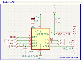
Part Number: ADS1015

Tool/software:

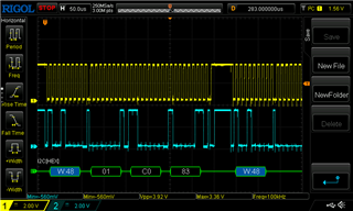
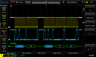
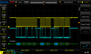
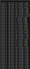
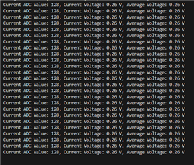
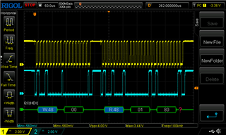
I am having an issue with my ADC. I am able to see the device but it is returning a value of 25. I have the gain set to 1 (4.096v) and the input voltage on channel 0 is 3.26v (verified with a multimeter) but the output is ADC value of 25 or 0.025v. All 4 channels output incorrect values. 

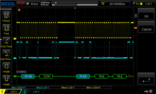
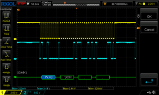
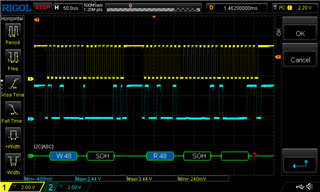
I noticed there is a lot of undershoot but I am not sure if that is just error from my oscope leads or probe placement. I noticed there is a ? at the end of the decoding as well. 

Any help would be appreciated.

Thank you!

  • Hi DBC,

    I will take a closer look at this and get back to you by tomorrow.

    Best Regards,

    Angel

  • I have some updated oscilloscope data. I have added the thermistor that channel 0 is supposed to be reading and verified with an DMM that the voltage is 0.68v which is correct for ~room temp. 

    My code requests the current value of channel 0 every 5 seconds. Out of many samples, only a few look correct. I have marked the outputs that are close to correct. 

    The images above are the same as below, but zoomed in. ^


    Here is the full transmission. ^

    Here is the output of my code with the outputs that are close, marked. 

  • I have updated this thread with more information. Please let me know:)

    Thank you!

  • I changed my code to use averaging, 128 samples per second and then output the average every 5 seconds to help get rid of any noise issues.

    It just outputs 128 over and over, and does not respond to any changes in temp (even though the input voltage is changing, verified by a MM.

    Really don't know what else to try other than maybe replacing the ADC with a new one. When I change the FSR to a different value, the output does change so the ADC is working to a point but I'm wondering if the inputs are damaged from the under/overshoot?

  • Hi DBC

    It is possible that the part may be damaged if there is over/undershoot that exceeds the recommended operating conditions of the device, but it think the problem here is that the data is being interpreted incorrectly.

    First you mention that you are setting the device to 4.096V FSR, but from your oscilloscope capture it seems that what you are writing to the configuration register is a FSR of +/-6.144V. You are also setting the device to start a single conversion but also setting it to operate in continuous conversion mode. I would recommend setting the device in single-shot mode. 

    You are issuing a read conversion result command immediately after issuing your configuration setting. You might need to add a longer delay before issuing the read conversion register command, as the conversion result might not be ready when you issue the register read.

    Also make sure that the data is being interpreted correctly, since the device is 12-bit but the data is read through two 8-bit frames, the last 4 bits (which are always zero) should be ignored.

    Best Regards,

    Angel

  • After more troubleshooting, I think you might be right. I am able to get the correct output most of the time, but I have to restart the device sometimes to get it to stay stable and when the input value changes quickly the output gets really unstable. 

    Do these oscilloscope captures look like I have signal integrity issues?

    Thank you for the response!

  • Here is my code:
    #include <Arduino.h>
    #include <Wire.h>
    const int ADS1015_ADDRESS = 0x48; // Default I2C address for ADS1015
    const int CONFIG_REGISTER = 0x01;
    const int CONVERSION_REGISTER = 0x00;
    const float GAIN = 4.096;
    const double INPUT_BIAS_V = 0.075;
    void setup() {
      Serial.begin(9600);
      Wire.begin();
    }
    void loop() {
      Wire.beginTransmission(ADS1015_ADDRESS);
      Wire.write(CONFIG_REGISTER);
      Wire.write(0xC3); // MSB: single-shot mode, ±4.096V, single-ended channel 0
      Wire.write(0x83); // LSB: 1600 SPS, disable comparator
      Wire.endTransmission();
     
      delay(15);
      Wire.beginTransmission(ADS1015_ADDRESS);
      Wire.write(CONVERSION_REGISTER);
      Wire.endTransmission();
      Wire.requestFrom(ADS1015_ADDRESS, 2);
      int16_t result = 0;
      if (Wire.available() == 2) {
        result = (Wire.read() << 8) | Wire.read();
      }
     
      float voltage = result * GAIN / 2048;
      voltage -= INPUT_BIAS_V;
      Serial.print("ADC Value: ");
      Serial.print(result);
      Serial.print("\tVoltage: ");
      Serial.println(voltage, 4);
      delay(1000);
    }
    
    Which is returning: ADC value: 448  Voltage: 0.8210
    The measured voltage is 0.698V on channel 0. The channel has a 0.075V bias. My latest capture wit this code snippet returns "[W:48] [NUL]" so I think my oscope is having a hard time decoding it?
  • Hi DBC,

    You may be just seeing some error from the oscope leads or probe placement rather than having signal integrity issues.

    Are you able to provide scope (or logic analyzer if possible) captures of your digital communications that correspond to the readings you are referring to?:

    Which is returning: ADC value: 448  Voltage: 0.8210

    This will help clarify if you are interpreting the data from the ADC correctly.

    Best Regards,

    Angel

  • Sorry for bouncing all over the place but I have been troubleshooting in-between our communications.

    So I think I found the issue. I wrote a simple program:

    Point to 0x01 configuration register,

    write 0xC5

    write 0x83

    short delay

    read 0x01 register (returns 0x181)

    So it doesn't seem to be taking the configuration? which would explain my weird readings. 

    Here are the captures from the above code:

  • Hi DBC,

    Let me take a look and I will get back to you early next week.

    Best,

    Angel

  • I appreciate it. 

    I forgot the delay in the above captures but after that, I tried adding a delay right after reading the first time so:

    Point to 0x01 configuration register

    write 0xC5

    write 0x83

    read

    short delay

    read

    Both reads come back with the same 0x181. 

    I swapped the ADC with a new one and still am getting the same results, so I may  have a communication problem or something killed both ADCs. I'd hate the try another before knowing what is going on. 

  • I finally figured it out. 

    I also have a DAC121 on the same I2C bus that was causing issues. 

    I have the ADC address set to 0x48 and the DAC address set to 0x09. I checked the "do not use" addresses in the DAC datasheet and it doesn't say you cannot use 0x48 when using the 0x09 address. 

    Do you know why this would be an issue?

  • Hi DBC,

    Glad to hear the issue is gone. I'm not too familiar with the DAC121, but you could post a new E2E question for that part and the DAC team will be able to help point out if there are potential issues with that part.

    So after DAC121 is removed from the I2C bus, ADS1015 now works as expected and you can retrieve ADC readings properly?

    Best Regards,

    Angel

  • Yessir, everything works as soon as I depopulated the DAC IC. 

    I will do that if I can't figure it out. 

    thank you!