DAC63001: DAC63001 used for Voltage margining ...

Part Number: DAC63001
Other Parts Discussed in Thread: DAC63204EVM, DAC63202, DAC63204

Tool/software:

Hi,

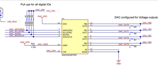
We are looking to use DAC63001 to voltage margin a DC-DC converter. The scheme is similar to the one described in Section 8.2 of the Datasheet.

Our use case is as follows:

1. Power the System

2. Set the DAC so that the output voltage from the DC-DC is set at +3%

3. Save the DAC value in its internal NVRAM

4. Power off the system and power it again - expectation is that the DC-DC output should be at +3% or the value set by the DAC

Our thinking is that if we use the Power Good (PG) after inversion of the DC-DC to enable the DAC after a small amount of slew by connecting it to GPIO (pin 5).

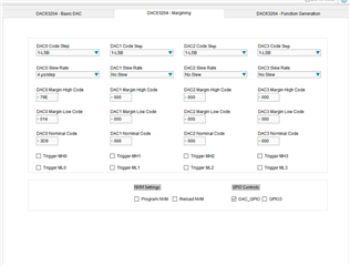
Can you advise if this is possible and if yes - what should the GPIO pin of the DAC be configured as. The datasheet seem to suggest several modes such as PROTECT, LDAC etc.

 Thanks

  • Illia will help you here.

  • Hi Ranjeet, 

    Thank you so much for reaching out. 

    This function is definitely achievable with DAC63001. 

    First of all, you can program the DAC output level on the power-up by writing to DAC-0-DATA Register. Then write to DAC-0-MARGIN-HIGH your +3% value. Then configure your GPIO (GPIO CONFIG register) MARGIN high-low (1010 binary) to configure the GPIO to trigger margin high operation, and then configure your slew rate control.

    Please refer to this tech note for more information on how to get the device up and running. While it is created for 4-ch it should be identical for a single channel version of the device as well. 

    Please let me know if you need any additional help. 

    Thank you, 

    Illia Volkov 

  • Hi Illia, 

    I was able to trigger margin high and margin low by manually triggering the 'COMMON_DAC_TRIGGER' register. Is it possible for the DAC Vout value to return to Nominal value? How can I achieve this? e.g. DAC0 margin high = 1.19V, DAC0 margin low = 0.012V and DAC0 nominal = 0.6V.

  • Hi Syasya, 

    To return to the nominal value, you need to rewrite the code to the active register (DAC DATA register). The trigger will only switch between the margin high and margin low levels. 

    Best,

    Katlynne Jones

  • Hi Katlynne, 

    Thanks for your answer.

    I have been testing this feature with DAC63204EVM where I am triggering margin high and margin low  e.g. DAC0 margin high = 1.19V, DAC0 margin low = 0.012V. I am able to trigger margin high/low using the GUI buttons (shown in the screenshot I attached in the above thread). 

    Now, I am trying to trigger this margin using rising/falling edge at GPIO pin but not having much luck. I am triggering this by inputting high (2.5V) or low (0V) signal into GPIO pin 5. For this evaluation board, I desoldered R1 and set the registers to:

    Register Name Register Address Hex Value  Decimal Value
    DAC_0_MARGIN_HIGH 0x01 0x79e0 1950
    DAC_0_MARGIN_LOW 0x02 0x0140 20
    COMMON_CONFIG 0x1F

    0x1249

    GPIO_CONFIG 0x24

    0x0115

    The GPIO doesn't seem to detect the rising/falling edge signal. Am I missing something ?

  • Hi Syasya, 

    You are using channel 0 on the DAC63204EVM? Try writing 0x0035 to the GPIO config register. You are enabling the GPIO function on channel 3, not channel 0. I assume this is why you are not seeing any effect on channel 0. 

    Also, if you are applying an external high/low trigger to the GPIO pin, remove the shunt from J6. When J6 is closed, the GPIO pin of the DAC is connected to one of the GPIO pins of the FT4222 on board controller. 

    Best,

    Katlynne 

  • Thank you Katlynne. Yes that is right I'm trying to use DAC0. It is working now! 

    What confused me was the SMART DAC GUI shows the descriptions below: 

  • Hi Syasya, 

    Thanks for pointing that out. The field names are correct, GPI1_CH3_SEL corresponds to channel 3, but it looks like the descriptions have them in the opposite order. I'll mark that to be fixed. 

    Another thing I'll point out is that the pinout is slightly different between the four channel devices and the two/one channel devices. See below the DAC63304, DAC63202, and DAC63001 pinouts from left to right. When you move over to the DAC63001 you'll need to look at the DAC63001 datasheet to make sure you're using the correct registers.  

    If you were to use the DAC63204 GUI settings for the DAC63001, you would use all of the settings that correspond to channel 3 on the GUI because these are the settings that match up to channel 0 on the DAC63001.

    Best,

    Katlynne