ADS7038-Q1: Manual mode: clarification needed about oversampling

Part Number: ADS7038-Q1
Other Parts Discussed in Thread: ADS7038

Tool/software:

Team,
Could you please help with the below?

we have now decided to use the manual mode and to secure the data with a CRC at the SPI interface.
The settings used:
    Manual mode: SEQUENCE_CFG_Register = 0x00
    CRC  enable: GENERAL_CFG_Register = 0x40
    Enable append status: DATA_CFG_Register = 0x20
    Oversampling: OSR_CFG_Register = 0x07
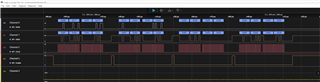
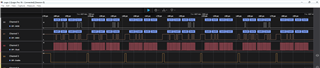
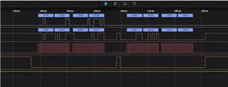
This works so far, we read 16 bit data and see 4-bit status and the CRC sum. CRC sum fits.
If we append the channel ID to the data instead of the status, we also see what is expected. The CRC is also correct then.
 
Now the questions:
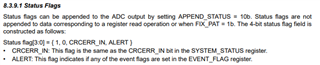
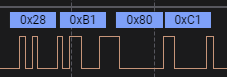
1)Nowhere in the data sheet does it say which status bits are in which position in the 4 appended status bits.
I read 0x80 (which would already be 8 bits and not 4 and I cannot read from the read out from the data sheet at which bit position which status is).
-Could you clarify?


We work in manual mode with oversampling.
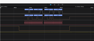
2)Where can I see whether the oversampling sequence has already been completed?
3)n this case, is oversampling also started with the rising edge of the CS  or do I have to start the sequence separately (SEQ_START in SEQUENCE_CF_Register)?

Thanks in advance,

Anthony

  • Hi Anthony,

    1. The order of the status flags are described in section 8.3.9.1 of the datasheet. I've included it below for reference. Table 8-6 in section 8.3.9 also describes the output data format. When CRC is enabled, it should be noted that the SPI frame is 32 bits long.

    2. The status of the oversampling sequence can be done by polling bit 3 (OSR_DONE) of register 0x0 (SYSTEM_STATUS).

    3. Setting SEQ_START is not necessary when using the device in manual mode. When using the OSR module, the first conversion is triggered manually with the rising edge of CS, and successive conversions are triggered by an internal oscillator. 

    Regards,
    Joel

  • Hi Joel,

    many thanks for the answer. 

    I have an additional question concerning the oversampling:

    Table 8.2 shows the clock settings to configure the internal conversion rate. Is this table also applicable for the manual mode to control the sampling rate for the oversampling? If not, on which sample rate are the consecutive conversions performed following to the first conversion which is triggered from the rising edge of the CS?

    What i did in the meantime:

    i implemented the polling of the OSR Flag and i set the oversampling rate to 128 (OSR = 0x07).

    What i see on the SPI interface is that:

    1. frame sets the channel ID to 0.

    2. frame sends the read command for register 0.

    3. frame read the register 0 => status == 0x80 => oversampling finished

    4. frame read the sample data

    as i mentioned, i set the OSR to 128, i would expect that OSR will take at least 128us. The OSR-Flag should be set at the first read after starting the conversion. Additionally the convertiondata (0xEF8A) seams to be wrong, the analog voltage is set to 500mV with AVDD at 3,3V.

    What is wrong with the sequence?

    Thanks in advance

    Thomas

  • Hi Thomas,

    Yes, the CLK_DIV and OSC_SEL fields is applicable to manual mode.

    In frame 3 of MOSI (which reads 0x80 0x89), the first byte is the register value and the second byte is the output CRC. In point 3, are you saying that 0x80 is indicating that the oversampling is finished? A 0x80 read from register 0x0 means the only high bit returned is the RSVD bit, which always returns high, so oversampling would not be done at the time of this read. Let me know if I misunderstood this. Register 0x0 should read 0x88 when OSR is done. 0x89 looks to be the 8-bit CRC for 0x80.

    Could I see the logic capture where you actually configure OSR?


    Regards,
    Joel

  • Hi Joel,

    thanks for the response. Yes you are right, the STATUS Register should be 0x88 when OSR is done. My fault. And 0x89 is the CRC, correct.

    But the OSR Bit will never be set. I read 0x80 from the status register forever.

    Here ist the frame where i configure the OSR:

    And the readback of the register shows that the register has the correct value:

    Regards

    Thomas

  • Hi Thomas,

    Thanks for the screen captures. I couldn't quite notice anything wrong with your setup or start of conversion. Are you able to export the logic capture as a .sal file and attach it here, so that I can take a closer look at the entire transmission?

    Regards,
    Joel

  • Hi Joel,

    attached the complete SALEA file.

    Hope it helps.

    After starting the sampling you can see that i constantly read the status register. During sending the read command the chip sends back data. When you take a look at the data, you see that after some reads (ca. 300us) the chip returns a different value. The time fits to the oversampling rate together with the clock settings, and the value fits to the analog value that is applied to channel 1.

    So this fact let me believe that the conversion is completed. However the OSR_DONE flag will not be set.

    The analog values shown in the analog saleae channels are applied to the analog input channels of the ads7038.

    Thanks for your help

    Regards 

    Thomas

  • Hi Thomas,

    Thank you for letting me know. I'll investigate whether this falls under the normal operation of the device.

    Regards,
    Joel

  • Hi Thomas,

    I've taken a look at the file you sent, and thank you for your patience with this. Have you tried initiating a normal conversion from the device without giving it any commands via SDI? If so, could you send the logic capture file of you taking regular conversions from the device after all the register configurations? As you said, this conversion seems to indicate that the OSR conversion is already done since 0x28B1 is a 16-bit result, yet the OSR_DONE bit does not go high. 

    My other suspicion is that the oversampling is indeed done for the current conversion, but the OSR_DONE bit remains 0 as the oversampling for the next conversion is in progress. 

    Regards,
    Joel

  • Hi Joel,

    i have sent an additional SALEA log to Marcela.

    In this log i have configured the manual mode and i tread the device exactly as described in the datasheet. After initialization, reading the data and switching to the next channel (writing MANUAL_CHID) is just one SPI cycle (as the datasheet describes in Figure 8-15. Starting Conversions and Reading Data in Manual Mode).

    Oversampling, CRC and appending of the status is enabled. This mode works as expected. However due to the fact that the OSR flag is not part of the appended status flags, there is no indication that oversampling has finished. 

    When polling the status register, it is not clear what happens with the extra chip selects. Does they start new conversions? Do they interrupt running conversions? So i think it is not an option at all to poll the status register while the device is in manual mode.

    Regards

    Thomas

  • Hi Thomas,

    Thanks for this. These are interesting results. I'm not too sure on the answer to your questions as well. Allow me some time to write my own SPI sequences into this device and evaluate if the OSR_DONE bit will ever go high. I'll get back to you at the earliest opportunity.

    Regards,
    Joel

  • Hi Joel,

    did you have a chance to setup your own SPI sequence?

    Thanks,

    Thomas

  • Hi Thomas,

    I haven't quite yet. I expect to have this by this by the end of the week. This seems like a common concern with this device, so I'll make sure to update you right away with my conclusions. Thank you for your patience and cooperation in this.

    Regards,
    Joel 

  • Hi Thomas,

    I haven't been able to get the OSR_DONE bit to be set to high during manual operation of the device. Currently, I'm unsure if this is to be expected and it will go high by some other conditions or in another mode, or if this functionality is just not implemented in the device properly. There is also the possibility that there is a timing component relevant to when this bit turn high and then goes low.

    The writer of this datasheet is on business travel, but I will communicate your issue to him at the soonest convenience and determine if this bit is functional.

    For now, are you able to proceed with your design without polling this status bit?

    Regards,
    Joel

  • Hi Joel,

    yes we can proceed without polling. However it is a safety drawback not to know reading actual data. For now we treat the device as described in the datasheet (Figure 8-15). Requesting a new channel and reading data is just one SPI frame to avoid multiple CS. Appending CRC and Channel ID is enabled. Oversampling is also enabled. We simply wait the calculated time for oversampling should be finished. CRC errors are detected by detecting that the requested Channel ID is not returned within the data frame where it is expected.

    So, both mechanisms (detecting CRC errors by checking the returned channel ID, and simply waiting the oversampling time without polling a direct indication) are not really perfect, especially for a safety Application. But it is the best solution we have right now. 

    Regards

    Thomas