This thread has been locked.

If you have a related question, please click the "Ask a related question" button in the top right corner. The newly created question will be automatically linked to this question.

ADS131A04: Unable to achieve the samples reception in 128Ksps and 64 Ksps

Part Number: ADS131A04

Tool/software:

Hi, I am using the ADS131A04, 16-bit with 4 channel asynchronous interrupt mode,

ADC configurations are:

0x0B     A_SYS_CFG  0x78 (VCP off, High res EN, VREF4V, INTVREF)

0x0C     D_SYS_CFG 0x3C

0x0D     CLK1 0x02 (CLK_DIV=2) 16.384/2=8.192M

0x0E     CLK2 0x2F (ICLK_DIV=2, OSR=32) fmod = 8.192M/2 =4.096M, sampling rate 4.096M/32=128ksps

0x11     ADC1  0x00 GAIN1 = 1x

0x12     ADC2  0x00 GAIN2 = 1x

0x13     ADC3  0x00 GAIN3 = 1x

0x14     ADC4  0x00 GAIN4 = 1x

0x0F     ADC_ENA 0x0F (all ADCs on) 

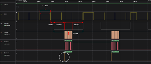
The required sampling rate is 128k samples/sec, but I am not able to get the 128k samples/sec; I am only getting a maximum of 29k samples/sec. Even with 64k samples/sec we are getting only 29K samples.

Here we are using Master device as the Renesas RA6M3 and using a spi clock speed of 15 MHZ.

Please let us know on this what are the other configurations needs to be considered and provide suggestion to achieve this 128ksps.

Thank in Advance

  • Hi ,

    Welcome to the E2E forum. Are you using a single ADC? Could you please provide the timing of SPI bus (/DRDY, /CS, SCLK, DOUT and DIN)?  A timing captured with a logic analyzer would be good. Your schematic will be helpful so I can look at your hardware configuration.

    BR,

    Dale

  • Hi Dale Li, Thank you for your acknowledgement.

    I am using the ADC with RA6M3 eval kit. The ADC module is plugged into the RA6M3 device, and the complete module has 3 slave devices. One of the slave devices is the ADS131A04 ADC.

    Please find the logic analyzer capture for 128K & 64K samples.

    Thanks

    adc_sampling_rate.zip

  • Hi Manohar,

    Thanks for sharing your timing. Please see my feedback and suggestion below.

    1. Your A04 ADC is working as expected, it operates at 128ksps data rate, see the period of T highlighted on the /DRDY signal which is the output signal from the ADS131A04 ADC, it indicates the period time for a new available data is T=7.8us which indicates the data rate is 1/7.8us=128ksps.

    2. Your microcontroller is missing to read the data from the A04 ADC, see the timing below. Your software code on your microcontroller creates too long delay (delay1, delay2 and delay3) for reading one conversion data, your microcontroller is taking T-real time to read one data which is much longer than the required time to retrieve the conversion data from the ADC, T.

    3. In order to read the STATUS and the data of 4 channels, the pulse on the MOSI pin before reading the data is not needed. The ADC only requires SPI clocks to shift out the STATUS word and the conversion data.

    4. You can also use CPOL=0 and CPHA=1 SPI configuration to communicate with the ADS131A04 ADC.

    BR,

    Dale

  • Hi Dale Li,

    Thank you for your valuable feedback & suggestions, we will verify and we will come back.

    Thanks

  • Hi Manohar,

    Let me know if you have any further question.

    BR,

    Dale