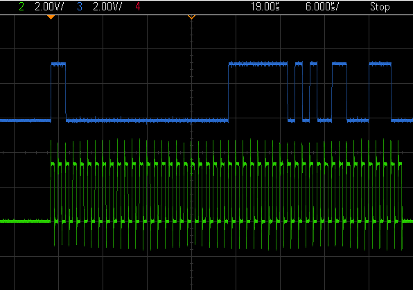
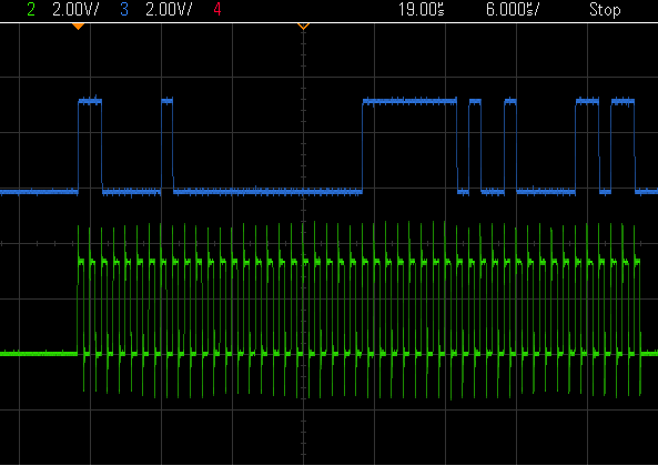
Tool/software:
Hello,
I'm currently running into a problem when trying to read the LOFF_STAT register after switching from AC leads configuration to DC leads configuration, where it always returns 0. However, when streaming with DC leads configuration enabled, the LOFF_STAT register in the STATUS portion of the stream returns the correct value. Additionally, when changing the configuration back to the AC leads configuration and reading back the entire configuration, it returns the correct value as well.
The AC Leads configuration set by default sets the registers to the following values:
// Binary Register Selected Options
// -----------------------------------------------------------------------------------------------------
CONFIG1: 0x03, // 0b00000101 Continuous, 1000SPS
CONFIG2: 0xF0, // 0b11110000 Test signal disabled, Internal *4.033V ref enabled, Leads Off enabled.
LOFF: 0xF5, // 0b11110101 70%-30%, 22 nA, AC lead off frequency F_DR/4
CH1SET: 0x00, // 0b00000000 6x Gain, Electrode input
CH2SET: 0x81, // 0b10000001 Power down, Input shorted
RLD_SENS: 0xE0, // 0b11100000 fMOD / 4 Chop Frequency, Buffer Enabled
LOFF_SENS: 0x03, // 0b00000011 Enable positive and negative
LOFF_STAT: 0x00, // 0b00000000 Read-only
RESP1: 0x02, // 0b00000010 N/A
RESP2: 0x07, // 0b00000111 N/A
GPIO: 0x00, // 0b00000000 Output low
Then we change the configuration and read registers using the following process:
1. Set PWDN/RESET low
2. Wait 8uS
3. Set PWDN/RESET high
4. Wait 36uS
5. Send SDATAC command
6. Wait 8uS
7. Wait an additionally 0.9S, then set LOFF to 0xF4
8. Wait 502mS, then read LOFF_STAT
9. Wait 1ms then set LOFF_SENSE to 0x13
10. Wait 502ms then read LOFF_STAT
11. Wait 1ms then set LOFF_SENS to 0x03
12. Wait 502ms then read LOFF_STAT
Is there any reason why reading the LOFF_STAT register individually with the configuration above shouldn't work?
All delays other than the 8uS and 36uS are necessitated by unrelated code, but I included them in case they could be helping/hurting the problem.
All LOFF_STAT reads described above return 0 despite the LOFF_STAT portion of the ECG stream returning 1 in the proper bits when streaming is enabled with the same hardware configuration.
I haven't included included my process for setting the register initially, but I include all of the delays described on page 40 of the ADS1291 datasheet (to my knowledge), and when reconfiguring back to the standard configuration above after this process, the LOFF_STAT register returns 1 in the proper bits. Lastly, if instead of only writing to individual registers, if I rewrite the entire configuration block instead of writing to individual registers each time under DC lead detect mode, I still read only 0s in the LOFF_STAT register, but I believe I have other problems there as well, as it then acts like stop continuous mode didn't work after re-writing the configuration, but I haven't dug into that too deeply.
My question is, is there anything I'm missing? Is there any reason why it would work in the streamed packet and not while reading an individual register/with the configuration I have? Is there any reason why rewriting the entire configuration at the end with all delays and resets shows the LOFF_STAT register values as 1 when the previous reads with the previous delays didn't return the right value?


