This thread has been locked.

If you have a related question, please click the "Ask a related question" button in the top right corner. The newly created question will be automatically linked to this question.

ADS7138-Q1: ads7138qrterq1

Part Number: ADS7138-Q1

Tool/software:

Hi,

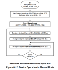
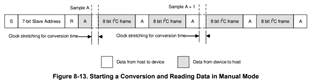
Please send me a flowchart how the ADC value is read, and the ADC value is read from which registers?

Thanks,

Chuan

  • Hi Chuan,

    Thanks for your question! We will get back to you in a couple of days as we are out of office due to the 4th of July holiday. Thanks!

    Best regards,

    Samiha

  • Hi Chuan,

    Here is the process of configuring and reading from the device in manual mode. This is described more in depth in section 8.4.2 of the datasheet.

    This is the sequence to read the output data stream from the device on the SDA pin.

    You also have the option to read most recent conversions for each channel from the register bank. Please consult section 8.6 of the datasheet to find the registers that relate to your desired operation. 

    To read and write registers, follow the format as described in section 8.5 of the datasheet. Please let me know if you require additional help with this. 

    Regards,
    Joel

  • Does the ADC Reading is from these register MAX_CH0_LSB, MAX_CH0_MSB, MAX_CH1_LSB, MAX_CH0_MSB, etc.?

  • Hi Chuan,

    No, this wouldn't represent the data that the device is currently capturing. This would be the maximum value from a given analog input (CHx) since the last time the register was read.

    The most recent value for a given input channel is found in the RECENT_CHx_LSB and RECENT_CHx_LSB registers, where x denotes the input channel. Note the full conversion value is spread across two 8-bit registers since this device outputs 12-bit data. 

    However, real-time data is read from the SDA pin using the sequence as described above.

    Regards,
    Joel