ADC08D1000: Regarding FSR/ECE pin, H/L voltage levels and the timing at power-on

Part Number: ADC08D1000

Tool/software:

Dear Specialists,

My customer is evaluating ADC08D1000 and encountering the problem.

I would be grateful if you could advise.

---

I'm encountering an issue with the ADC08D1000 where the settings differ from the circuit wiring when the power is turned on.

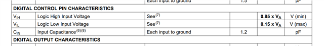
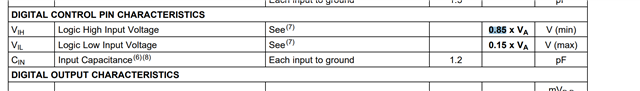
I'd like to confirm the specifications of the ADC08D1000's 14-pin (FSR/ECE) terminal.

According to page 11 of the data sheet

Low: Full-scale differential input 650mVp-p

High: Full-scale differential input 870mVp-p

When the power is turned on, it should operate at a full-scale setting of 870mVp-p, but sometimes it becomes 650mVp-p.

Currently, the wiring for pin 14 is shared with the power supply circuit.

I think this connection may be causing the problem.

Could you please tell me the voltage conditions for recognizing High and Low in normal control mode and the timing for reading the settings?

ーーー

I appreciate your great help in advance.

Best regards,

Shinichi

  • Hi Shinichi,

    See page 12 for voltage conditions for recognizing High or Low control on the ECE pin.

    It sounds like the power supply tied to this pin is noisy and not settling. Causing this pin to put the fullscale into a different state.

    Regards,

    Rob

  • Hi Rob,

    Thank you for your reply.

    I'll share your answer with the customer.

    When the customer has an additional question, I consult you again.

    I appreciate your great help and cooperation.

    Best regards,

    Shinichi

  • HI Rob,

    The customer has additional questions.

    Could you please advise?

    ---

    I would like to know when the formula (0.85 x VA) for the VA pin becomes effective.

    At what V does VA have to be for the ADC internal input circuit to start operating and latch the data on pin14 (FSR/ECE)?

    For example, when the ADC power supply(VA) exceeds 1V, the internal circuit starts operating, and 100us later the Control Inputs take in the voltage and set the Control Logic, etc.

    ーーー

    I appreciate your great help and cooperation.

    Best regards,

    Shinichi

  • Hi Shinichi,

    I am not sure I understand your question.

    Do you mean for this portion of the datasheet?

    Regards,

    Rob

  • Hi Rob,

    Thank you for your reply.

    Let me rephrase the question.

    Could you please advise?

    ---

    (1) What is the VA threshold voltage at which the ADC08D1000's internal circuitry begins to operate?

    The datasheet says 1.8V to 2.0V, but I believe the actual operating voltage is lower.

    (2) When does the formula for pin14 (FSR/ECE) specifications (0.85 x VA) become valid?

    It depends on the value of VA, so a minimum value for VA is required.

    (3) Is there an internal latch function on pin14 (FSR/ECE)? 

    ーーー

    I appreciate your great help and cooperation.

    Best regards,

    Shinichi

  • Hi Shinichi,

    1) 1.8V is the lowest value, so that is when the internal circuitry operate appropriately.

    2) When 1.8V is stable, this highly depends on the power supply and devices used.

    3) No internal latch on this pin.

    Regards,

    Rob

  • Hi Rob,

    Additional information obtained from customer, could you please advise.

    The customer is experiencing a phenomenon where FSR/ECE(pin14) behaves differently from the settings during a power interruption test.

    Two behaviors were observed during the power interruption test (power interruption).

    When FSR/ECE(pin14) is recognized as high (green line), and occasionally when it is recognized as low (red line).

    In addition, when recognized as low, it does not become high even if the voltage becomes 1.8V.

    Power supply conditions for recognizing high control: 0.85 x VA = 1.53 [V]

    Power supply conditions for recognizing low control: 0.15 x VA = 0.27 [V]

    * VA is the minimum operating voltage of 1.8 [V]

    The blue line is the waveform of VA rising when the product is normally turned on.

    In this case, FSR/ECE(pin14) was not recognized as low.

     VA waveform.xlsx

    Could you please answer 3 questions listed below.

    (1) It seems to latch up when FSR/ECE(pin14) is recognized as low. Is there a possibility of latch up?

    (2) If FSR/ECE (pin14) is latched up, how can it be avoided?

    (3) Regarding the voltage waveform during a momentary power outage

    The voltage is rising without dropping to 0V, is this a problem?

    In the past, other devices have malfunctioned if the voltage did not reach 0V when the power was turned off.

    Are there any other problems with the voltage waveform?

    ---

    I appreciate your great help and cooperation.

    Best regards,

    Shinichi

  • Hi Shinichi,

    Please keep in mind that the customer should be following any/all power requirements & recommendations within the device datasheet.

    Per the datasheet, 14.6.1 Supply Voltage section:

    No pin should ever have a voltage on it that is in excess of the supply voltage or below ground by more than 150 mV, not even on a transient basis. This can be a problem upon application of power and power shut-down. Be sure that the supplies to circuits driving any of the input pins, analog or digital, do not come up any faster than does the voltage at the ADC08D1000 power pins.

    In the excel data, VA has a transient of 2.11V, which is above the rated threshold.

    Regards,

    Rob

  • HI Rob,

    Thank you for your reply.

    I understand that the waveform exceeds the operating voltage range of the VA, and in that case problems may occur when powering it on or shutting it down.

    I'll share the information with the customer.

    On the other hand, the customer has additional questions.

    Could you please advise?

    --- 

    We've been rechecking the datasheet and am investigating the possibility that it may be operating in extended control mode.

    From the datasheet, p. 5, Pin Descriptions
    When the FSR/ECE pin (pin 14) is at a voltage equal to VA/2, it operates in extended control mode.

    Is there a possibility that the VA power waveform I sent the other day will operate in extended control mode?

    If there is a possibility that it will operate in extended control mode,

    - Floating or a voltage equal to VA/2 → What is the exact voltage range?

    - How long after the ADC starts operating will it check the terminal state of pin 14 to determine the mode?

    ーーー

    I appreciate your great help and cooperation.

    Best regards,

    Shinichi

  • Hi Shinichi,

    Comments to the questions below:

    Is there a possibility that the VA power waveform I sent the other day will operate in extended control mode? RR: this is difficult for me to comment, I think the customer needs to really work on the power supply bring up of the device based on the waveform that was sent over. The power up waveform should be continuous, not monotonic as shown.

    If there is a possibility that it will operate in extended control mode,

    - Floating or a voltage equal to VA/2 → What is the exact voltage range? RR: if you tie the FSR/ECE pin to VA/2, then the device should be in extended control mode

    - How long after the ADC starts operating will it check the terminal state of pin 14 to determine the mode? RR: same time as the calibration cycle. Page 14 of the datasheet.

  • Hi Rob,

    Thank you for your reply.

    I'll share your answer with the customer.

    When the customer have an additional question, I consult you again.

    I appreciate your great help and cooperation.

    Best regards,

    Shinichi

  • Hi Rob,

    The customer conducted additional  test and has a question.

    Could you please advise?

    ---

    - How long after the ADC starts operating will it check the terminal state of pin 14 to determine the mode? RR: same time as the calibration cycle. Page 14 of the datasheet.

    Based on this information, we performed a momentary interruption test and confirmed the voltage of pin 14 (ESR/ECE) at the end of calibration using the signal of pin 126 (CalRun).

    we confirmed the voltage of pin 14 (ESR/ECE) at the end of calibration using the signal of pin 126 (CalRun).

    When power is supplied normally, the ADC performs automatic calibration at startup, so we were able to confirm that pin 126 (CalRun) becomes high during calibration.

    However, during the momentary interruption test, the signal of pin 126 (CalRun) did not become high after recovery from the momentary interruption.

    If the ADC's power supply had been cut off and operation had stopped due to a momentary interruption, automatic calibration would have been performed after recovery from the momentary interruption, but this is not what happened.

    We suspect that the ADC's power supply did not drop and it remained in operation, but the setting information of pin 14 (ESR/ECE) was lost.

    If this were to happen, would it be possible for it to operate in the initial state of pin 14 (ESR/ECE)? Also, will the initial state operate in full-scale range selection or extended control mode?

    ーーー

    I appreciate your great help and cooperation

    Best regards,

    Shinichi

  • Hi Shinichi,

    If the power supply is lost or interrupted on the ADC, then all the register writes and settings, etc will be lost.

    You will need to reconfigure the device as you intend to use it.

    The ADC does not have non-volatile memory.

    Regards,

    Rob

  • Hi Rob,

    Thank you for your reply.

    I'll share your suggestion with the customer. 

    When the customer has an additional question, I consult you again.

    I appreciate your great help and cooperation.

    Best regards,

    Shinichi