This thread has been locked.

If you have a related question, please click the "Ask a related question" button in the top right corner. The newly created question will be automatically linked to this question.

ADS1299: SRB and BIAS functionality in EEG

Part Number: ADS1299

Tool/software:

Hello,

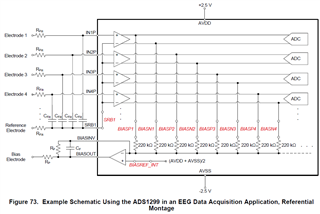
I am facing some problems understanding the funcionality of the SRB1, SRB2 and BIAS functionality. 

The purpose of the project is to read eeg data from the 8 Inputs.

It is possible to stablish the INxN inputs to the SRB reference? I would like to connect my electrodes only to the INxP inputs. If so, how should I modify the registers?

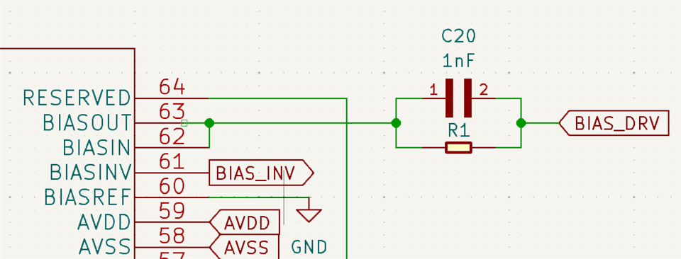
On the other hand, as I understand, BIAS is intended for giving a reference signal to reduce signal noise. But after reading the datasheet I still dont know how to configure it and connect it.

Any help?

Thanks!!

  • Hi Pablo,

    Please refer to Figure 73 below for single-ended configuration for the ADS1299. The channels register settings can remain configured as usual (Normal Electrode input, Gain = xxx). The only change you need to make is to write to the MISC1 register (15h) and set the SRB1 bit to 1b (bit 5). 

    The default settings for the BIAS amplifier configure it as buffer amplifier connected to an internal mid-supply bias voltage = (AVDD+AVSS)/2. This would be the simplest starting point. From there, it's possible to add some input electrodes to the common-mode derivation summing circuit by enabling the respective BIAS_SENSP and BIAS_SENSN register bits (BIASP1, BIASP2, etc.). Adding 2 or 3 input electrodes to the BIAS amplifier circuit can help to reduce common-mode noise interference that couples onto the body. It's not necessary to connect all input electrodes to the BIAS amplifier.

    Let me know if this helps!

    Regards,

    Ryan

  • Hello Ryan, 

    Thanks for your reply!

    About SRB1, if I turn up the MISC 5th bit, should I turn down the PD_REBUF bit from CONFIG3 register? or there is no relation between these two bits? 

    Withe regards to the BIAS, I have this scheme in the bias pinout from ADS1299:

    Instead of using any INx input, can be used BIAS_DRV as the BIAS pin? In that case, how should I make any change in the configuration?

    Thanks again!

  • Hi Pablo,

    BIASREF has no relation to the internal reference voltage (VREF). VREF is the ADC reference, which is compared against the differential input voltage to generate a proportional output code. The internal reference is powered down by default. An external reference can be used in applications which require higher accuracy or improved drift performance. Otherwise, you may enable the internal reference by setting the nPD_REFBUF bit to 1b.

    Regards,

    Ryan

  • Hi Ryan,

    And taking into account the BIAS scheme, could I use BIAS_DRV as Noise_cancelling pin and SRB1 as a Reference pin? 

    Do I have to change the configuration for this purpose?

  • Hi Pablo,

    Yes, the BIAS_DRV net name is directly the output of the internal BIAS amplifier. This signal is available on JP1.2 and JP17.1. The SRB1 input (i.e. reference electrode) can be connected to JP25 pin 6 with JP8 in the [1-2] position.

    Regards,

    Ryan