This thread has been locked.

If you have a related question, please click the "Ask a related question" button in the top right corner. The newly created question will be automatically linked to this question.

ADS1258EVM-PDK: Glitch on Channel 0 and ADC Overflow

Part Number: ADS1258EVM-PDK

Tool/software:

Hello,

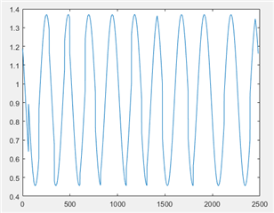
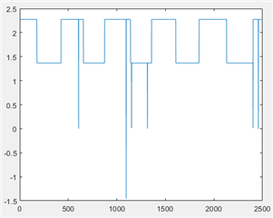
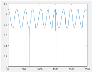
I'm using the ADS1258EVM with a sparkfun ESP32 Thing microcontroller to communicate between the PC and the ADC. I am controlling the ADC (sending commands, initializing) using MATLAB. I connected an AWG to one channel and measured the output but I'm seeing some issues: (1) Channel 0 glitches (Fig1) and (2) distortion. I input a sine wave with F = 10Hz, Vcm = 1V, Amplitude = 500mV. The Vcm and the amplitude is close to the input. I converted the codes to voltage by (Vswing/2^24)*code, where Vswing = 5V. I moved the same signal to channel 7 and I don't see any glitches (Fig2). I tried a square wave input to channel 0 and I still see glitches (Fig3). Maybe you have an idea what causes the glitches in channel 0. I have two EVM boards and they both behave the same. I'm using all 8 differential channels and I shorted to GND the unused channels. I even shorted Ch0 to GND but still I see some glitches (Fig4)

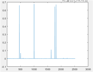
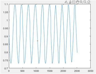
I also wanted to ask what could be a reason of occasional overflow in the ADC? Bit status 6 (overflow) and 5 (supply) goes high sometimes (example: 17 out of 20000 samples) but I'm keeping my input within the 5V range. I'm also using an external CLK and not the crystal. I still see some distortion on my sampled data even though it is just 10Hz sine wave signal (Figs. 5 and 6). I think it is caused by this overflow that I miss some samples.

Regards,

Patrice

 Fig.1: Ch0 Sine wave


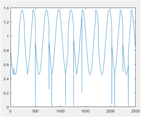
Fig.2: Ch7 Sine wave

Fig.3: Ch0 Sine wave
Fig.4: Ch0 grounded, still with glitches
Fig.5: Ch7, distorted output. Input: 10Hz
Fig.6: Ch0, same input with glitches
  • Hi Patrice Abbie Legaspi,

    If you apply these same signals to the EVM, and use the PHI controller + GUI instead of your controller, do you see the same issues? Or are the waveforms more consistent?

    Also, what are your register settings for these inputs?

    -Bryan

  • Hi Bryan,

    I don't see the glitch when I use the PHI controller + GUI. The waveforms are more consistent. I needed to use my own controller because I need to control the ADC through MATLAB so I was wondering what did I miss. I used 16MHz clock to the ADC clk using the AWG and set SPI clk to 8MHz. I did not connect the ADC clk though the SMA connection, just through the male header pin available. All GNDs are also connected (controller, ADC, supplies, clk).

    Here are my register settings:

    -CONFIG0: 0x02

    -CONFIG1: 0x03

    -MUXSCH: 0x00

    -MUXDIF: 0xFF

    -MUXSG0: 0x00

    -MUXSG1: 0x00

    -SYSRED: 0x00

    -GPIOC: 0x00

    -GPIOD: 0xFF

    I check if I initialized the ADC completely by connecting the GPIO to the scope. I see it go high (3.3V). I also read the registers after writing them, so I believe that I am able to write them correctly.

    Regards,

    Patrice

  • Hi Patrice Abbie Legaspi,

    The ADS1258EVM-PDK uses the same clock source for both the main ADC clock and SCLK. We observed some spikes in the data when clocks from different domains were used, which might explain the issues you are seeing. However, note that the spikes we observed were in the 100uV range, so not to the level you are seeing. But it is worth a try to see if clocks from the same domain improve the performance. This is also described in the datasheet:

    Also, ensure that there is a solid ground connection between the EVM, your controller card, and the signal source

    -Bryan