ADS124S08: BOCS switched off while converting?

Part Number: ADS124S08

Tool/software:

I use BOCS to detect broken sensors and observe unexpected behavior.
I proceed as follows: (very simplified example)
while(1){
INPMUX to Ch0(+) / Ch1(-) // set channel
System Control Register = 0b11110000 (BOCS = 10uA) // switch on BOCS
start_ADC() // start acquisition
while (not(DRDY)){} // takes about 100ms
read_out_ADC()
System Control Register = 0b00010000 // switch off BOCS
}
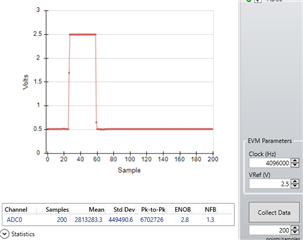
But the inputs are not pulled to VDD and VSS.
But if I set a delay before the acquisition, it works:
while(1){
INPMUX to Ch0(+) / Ch1(-) // set channel
System Control Register = 0b11110000 (BOCS = 10uA) // switch on BOCS
start_ADC() // start acquisition
while (not(DRDY)){} // takes about 100ms
read_out_ADC()
System Control Register = 0b00010000 // switch off BOCS
}
This gives me the impression that BOCS is disconnected from the MUX (AIN0 and AIN2) during the acquisition.
Can you confirm this?
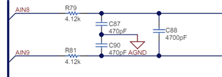
I have a 100nF CAP capacitance between AIN0 and AIN1.
I would expect this to charge up within the loop and maintain the voltage, even without the delay(5ms) before start_ADC(). But the longer the delay, the faster the CAP charges
  • Hi Andres Luder,

    I tried this on my EVM: I connected a 488kohm resistor between analog inputs AIN8 and AIN9

    Then, I turned on the BOCS set to 1uA. I measured a voltage of 0.488V across the input pins (using a DMM, not the ADC).

    Then, I disconnected the resistor while the BOCS were enabled, and the DMM immediately read 3.3V

    The inputs on the EVM look like the image below

    Can you try reducing the capacitance on the pin to see if the settling time decreases?

    It would also help to know if the voltage on the pins changes at all, or if the voltage is always 0 during the first test with no delay? Or does it approach 0, but just never get there?

    And how are you determining the voltage on the pins? Using a DMM to measure it directly, or using the ADC?

    -Bryan

  • Dear Bryan,

    thanks for your quick reply!

    In my case, the AIN values also go to VDD and VSS as long as I do not acquire with the ADC.

    It would be very interesting to know if you also get the 0.488V with the DMM even if you simultaneously acquire continuously (in a loop) with the ADC?

    As mentioned, in my case, the voltage drops as soon as I do that. The voltages actually do no "fall" to zero, but to values inside the valid measurement range so that I cannot detect a faulty (broken) sensor.

    Best regards

    Andres

  • Hi Andres Luder,

    Below are the ADC readings using the same configuration. I manually disconnected the resistor, then added it back. You can see the voltage goes to full-scale (2.5V) from 0.5V, and then immediately drops back down to 0.5V when the resistor is reconnected

    So no, I am not seeing you what you are seeing

    Can you try something similar and send your results so I can review?

    -Bryan