This thread has been locked.

If you have a related question, please click the "Ask a related question" button in the top right corner. The newly created question will be automatically linked to this question.

ADS131M02: ADS131M02: False data returned when communicate via SPI.

Part Number: ADS131M02

Tool/software: STM32CubeIDE

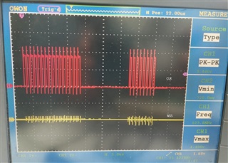
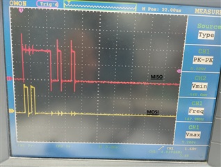
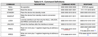
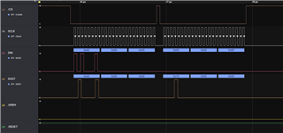
I have a query regarding ADS131M02.I used this external adc with STM32L496RGT6TR.I also done SPI interfacing with ADC.But i am stuck in whenever i tried to read registers reset value that time i get same value every time.For example i want to read device id for that i sent A0 command in response i received 2200h.Another one is status register for this i sent A1 command for this i received 0x500,but for other register i sent command that time i received 0x500 or any other value. Please Guide me.

  • Hi pavan lashkari,

    I saw your private message, however please keep the communication in this thread so other engineers can benefit from the thread in the future.

    As I requested, please provide your SPI timing plots for reading register (not your code), it would be good to include your /DRDY signal. Two continuous frames are needed because the register data should be shifted out by the ADC in the 2nd frame while your RREG command is sent to the ADS131M02 device in the 1st frame.

    BR,

    Dale

  • Hi pavan,

    I double checked your description about the register reading issue you are facing. Your command A0h is correct to read the ID register, but your command to read STATUS register (01h address) should be A080h, not A1h. Notice that the bit 12-7 in the RREG command are correct bits for register address as highlighted below. Another example is, your command to read GAIN register (04h address) should be A200h, not A400h. 

    Also, your command should be extended to 24 bits if your word size(length) configured on ADS131M02 ADC is 24 bits. Your /CS signal should be toggled for different frames. Below is a timing example to read GAIN register from ADS131M0x ADC, the correct RREG command was sent in the 1st frame and the GAIN register data was seen on the SDO in the 2nd frame:

    - Dale

  • Could you kindly tell me how to use RREG to build a command for Read multiple register and How we can read multiple registers ?

  • Hi pavan,

    If you look at the Command Definitions table I posted above, the command word for RREG is “101a aaaa annn nnnn”, where "a aaaa a" is the binary address of the register to begin reading and the "nnn nnnn" is the unsigned binary number of consecutive registers to read minus one. When you read a single register, "nnn nnnn" should be 000 0000b.

    For example, in order to read Gain register which has 04h address = 000 0100b, you command should be: 1010 0010 0000 0000, the red number represents the address of the GAIN register. The blue number are "nnn nnnn", 000 0000 represents only one register will be read. Therefore, the whole command is A200h. You will have to fill 0s for the rest 8 bits if your word size is 24-bit which is the default word size on ADS131M02 ADC. The final command word is A20000h, you can see this command word on DIN signal in my timing diagram above.

    If you could generate the same timing as my timing from your microcontroller, you should be able to successfully read a register from ADS131M02. Once you are able to read a single register, you can modify "nnn nnnn" to read more continuous registers with one command word.

    Let me know if you have any more questions.

    BR,

    Dale

  • Hi Dale,

    I attempt to read channel-0's input voltage.I try to adjust the input voltage with a potentiometer, but I never get the right value.So, whatever step do I need to perform in order to read the input voltage? and instruct me on writing in any register as well?

    Regards,

    Pavan

  • Hi pavan,

    I have showed you the the details (correct command and timing) to read a register from this ADC. Did you follow them and try? Was your register writing working? If not, please provide your timing for writing so that I can check. 

    Reading a register is similar as register writing, you can check the Command Definitions table above. Let me know your command to read a register and provide your timing if it did not work.

    I would suggest you to read channel data after your register writing and reading work as expected, so that can make sure your SPI communication is good.

    - Dale

  • Hi Dale,

    I attempt to write 0x0F0E in the clock register using the register writing technique you provided in the previous thread.I receive a result of 0x418000.However, I'm not sure why we're not receiving the identical write and read register values.Could you please tell me how to read that written value ?.

    Best Regards,

    Pavan

  • Hi pavan,

    When you write 0x0F0E to the CLOCK register which has 03h address, I assumed you were sending the following command + data to the ADS131M02 ADC:

     0110 0001 1000 0000  ->  0000 1111 0000 1110 -> to ADC

    You should expect a response from ADS131M02:  010a aaaa ammm mmmm which is 0100 0001 1000 0000, so the 0x418000 you received is a correct response from ADS131M02 ADC. The information are stated in the section of 8.5.1.10.8 WREG (011a aaaa annn nnnn) in the ADS131M02 datasheet.

    In order to read a register, you need to send a RREG command to read it. The ADC does not shift out the data of a register while you write it. I would recommend you to check all the details in the ADS131M02 datasheet.

    - Dale