


Tool/software:
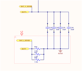
We're using AMC1303M2510 in our converter for DC current sense. We designed the circuit for operating range of 100Amps DC. While checking for SDFM data, I'm getting some variations in digital data.
1. When I was testing, i had directly connected the external wire and passing DC current by soldering directly on the SMD pad of resistors the data was coming quiet good.
2. When I was applying the same DC current but on directly on top of SMD resistors. And without running the converter the data was not coming right.
Here, in both cases the DC current is passing through the sense resistor of1.5mOhm 3 in parallel. By calculation the equivalent resistance has to come 0.5mOhms. But, by the data what we're getting the resistance seems like 0.7mOhms, we're assuming like because of the ENIG coating and the solder material quality the resistance might increased. So, can you please figure out what's can be the reason why we're getting increased value in SDFM and whether our assumptions are right or not. Help me resolve this issue. Thank you.
