This thread has been locked.

If you have a related question, please click the "Ask a related question" button in the top right corner. The newly created question will be automatically linked to this question.

ADS1256: Analog Sensor Analysis

Part Number: ADS1256

Tool/software:

Hello E2E Support,

I am attempting to collect data from an analog sensor with the ADS1256 through the attached PCB schematic (see attached datasheet for analog sensor specifications). I am performing a static Allan Variance analysis on the sensor data to see if my analog to digital conversion is sufficient to provide the same specifications as stated on the datasheet. Unfortunately the ADev plots do not seem to line up with what I would expect based on the sensor's datasheet. Is it possible that I need to improve the analog interface to the ADS1256 based on the PCB schematic and sensor recommendations?

Here are the connections between the sensor to the ADS1256 PCB:
Vcc: +5VDC
GND: Ground
Rate: PCB AIN0 Header Input Pin
REF: Ground
REFL: Ground
Temp: PCB AIN3 Header Input Pin
FRQ: Not connected (NC)
The PCB ground plane is then connected to the AIN7 header input pin for differential channel measurements of the rate output and temp output with respect to ground from the sensor.
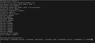
Register Config and Sensor Data:
Sensor Datasheet:
ADS1256 PCB Schematic and Layout:
Current ADev:
  • Hi ThePhysX,

    I am not an expert on angular rate sensor and the corresponding terminology, however if you can help convert to voltage I should be able to offer you more help. Specifically, what is the output voltage range you expect from the sensor, and what is the measurement resolution you expect from the ADC (in volts)?

    Also, can you provide the ADC register settings you are using?

    -Bryan

  • Hello Bryan,

    Thank you for looking into this question, here are the byte frames for the configuration registers:

    The rate voltage output varies +-2.4 VDC with respect to the REFL output. The offset voltage in the above screenshot is the static output voltage that I average for 5-10 seconds before making rate measurements.

    Thanks,
    PhysX

  • Hi ThePhysX,

    Thanks for providing this information. I see that you provided the register settings in your original post, apologies for overlooking that

    The rate voltage output varies +-2.4 VDC with respect to the REFL output.

    Are you saying that the applied ADC voltage can range from -2.4V to +2.4V with respect to AGND? If so the ADS1256 cannot support voltage below ground i.e. true negative voltages. The ADS1256 does support differential negative voltages i.e. when the voltage on AINN > AINP. I just wanted to make sure this is clear

    Also, what is the measurement resolution you expect i.e. how finely do you need to resolve the 2.4V measurement?

    -Bryan