ADS7128: How to correctly use RMS

Part Number: ADS7128

Tool/software:

Hello.

I'm fighting with the ADS7128 I2C ADC, and I'm unable to get the RMS to work. Reading Recent value works for me (on channels 0-2 which I use).
I tried to look for some example, but on github there is only .h file (which is even missing RMS_DONE and RMS_EN definitions) and no C code.

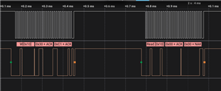
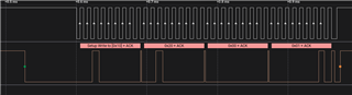
For faster testing, I'm using Python now, but the flag RMS_DONE (0x10) in SYSTEM_STATUS register is never 1.

Here is the Python example:
Thank you

from smbus2 import SMBus
from ads7128_defs import *
import time

bus = SMBus(1)

# reset for sure
bus.write_i2c_block_data(ADSI2C_ADDR, WRITE_SR_CODE, [GENERAL_CFG_REG, RST])
time.sleep(1)

# manual selection of channel
bus.write_i2c_block_data(ADSI2C_ADDR, WRITE_SR_CODE, [CHANNEL_SEL_REG, 0])

# Enable DC SUB in RMS
bus.write_i2c_block_data(ADSI2C_ADDR, SET_BIT_CODE, [RMS_CFG_REG, RMS_DC_SUB])

while True:
# enable RMS
bus.write_i2c_block_data(ADSI2C_ADDR, SET_BIT_CODE, [GENERAL_CFG_REG, RMS_EN])
# wait for RMS done
rmsState = 0
while rmsState == 0:
bus.write_byte_data(ADSI2C_ADDR, READ_SR_CODE, SYSTEM_STATUS_REG)
rmsState = bus.read_byte(ADSI2C_ADDR) & RMS_DONE
# read Recent ADC value, this works, so conversion should be started
bus.write_byte_data(ADSI2C_ADDR, READ_MR_CODE, RECENT_CH0_LSB_REG)
blsb = bus.read_i2c_block_data(ADSI2C_ADDR, 0, 2)
print("recent: " + str(blsb))
print("rmsState: " + str(rmsState))
time.sleep(1)
bus.write_byte_data(ADSI2C_ADDR, READ_MR_CODE, RMS_LSB_REG)
rms = bus.read_i2c_block_data(ADSI2C_ADDR, 0, 2)
print("rms: " + str(rms))
time.sleep(1)
  • Hi Daniel,

    I'm glad to hear you were able to take a look through our GitHub page! Example C code for this device is currently in the works, but it is not as of yet ready to share.

    As I'm not familiar with the Python library that you've imported, it would be best if you could share a logic capture of the I2C communication lines, SCL and SDA. This will make it easier to debug by observing the actual I2C communications at a low level, and isolating any problems from the code itself. I've seen some cases where the functions do not execute the sequence that you would expect from them according to the documentation. 

    Regards,
    Joel

  • Hi Joel,

    Thanks for fast response.
    I will have analyzer available again next weak, but what I already analyzed, only problem is the "stretched" read, from datasheet:

    There is no function like this in the python, only one byte read (read_byte).
    But the read_i2c_block_data function with register 0 (which do first standard write reg 0 and then read) works for the recent value read.

    Otherwise the combination of bus.write_byte_data and bus.read_byte looks in analyzer exactly how it should from datasheet.
    I have this combination used many time for checking that the registers are set properly, I just excluded it from the example to not be so long :)

  • Hi Daniel,

    Thanks for the update. Usually, an I2C peripheral on a microcontroller will be smart enough to handle the clock stretching. Clock stretching in essence is the ADC device holding the SCL line low to indicate it still has an ongoing operation, and it will release it when it is done to let the controller drive the SCL line high again. I would expect your read function to be able to handle this as well, but maybe it does not depending on the implementation from the library. I should be able to figure that out from the logic capture.

    Feel free to respond back when you are able to capture those sequences, and I'm happy to take a closer look.

    Regards,
    Joel

  • Ah, now I understand what the stretching means (sorry, I'm pretty new to I2C). I thought that the clock is still running, because I was confused by the definition "A new conversion is initiated on the ninth falling edge of SCL" in datasheet. But this ninth falling edge is in the datasheet described also as "Conversion Start Frame" in the diagram right?
    What I found here, I just should write two bytes of dummy data (and it's probably reason why the function read_i2c_block_data works for the recent value fine): e2e.ti.com/.../ads7128-how-to-send-conversion-start-frame-conversion-read-frame

    Is true that I saw this small stretching on oscilloscope already when reading single register.

    I will post next week some screenshots from the analyzer, now I have my wife in the maternity ward :)

  • Hi Daniel,

    I think all that the ""ninth falling edge of SCL" denotes is marking the start of the next conversion period once data for the current conversion has been read out. In terms of implementing your I2C functions, I don't think it will be too important, unless the clock stretching that happens after is problematic to your controller's logic.

    I'm a little bit confused by the description in the link you posted to myself. Writing/reading registers and reading data from the device are distinct in that the register read/write has the "write" bit after the 7-bit I2C address, while reading conversion data has the "read" bit after the 7-bit I2C address. I think that would be the reason to why you get conversion data by doing a block read.

    Lastly, congratulations on welcoming the newest member of your family! Take all the time you need in your response, and we can discuss later.

    Regards,
    Joel

  • Hi Joe.

    Here are photos (combined together for better clarity) of the analyzer of "one cycle" of the program, which do this:
    - manual selection of channel 0 (set value 0 to CHANNEL_SEL register)
    - set bit RMS_DC_SUB in RMS_CFG register
    - read RMS_CFG back to check it's written correctly
    - enable RMS by set bit RMS_EN in GENERAL_CFG register
    - read recent data ADC measurement as 2 words (this returns 128, 0 values, as I don't have anything connected now to the input, so the voltage is in the middle)
    - read SYSTEM_STATUS register to check the RMS_DONE bit
    i.postimg.cc/.../RMS-ADS.jpg

  • HI Daniel,

    Can you resend the photos as an attachment? Unfortunately the image hosting site you posted on is blocked on our networks.

    Regards,
    Joel

  • Hi.

    Sure, here it is :)

  • Hi Daniel,

    I think the reason why you never see the RMS_DONE bit get set is because, when in manual mode, you need to manually take all the conversions required for the RMS calculation. Setting the CNVST alone does not accomplish collection of all the samples required for the RMS calculation. 

    Bob does a great job of detailing this in the forum post below (see the table towards the bottom). You also have the option of using the device in autonomous mode, which might be easier to accomplish rather than manually collecting all the samples necessary.

    https://e2e.ti.com/support/data-converters-group/data-converters/f/data-converters-forum/1194057/ads7128-rms-module-not-working-as-expected

    Let me know if implementing that sequence gets you good results, and feel free to reach back out for more clarification. 

    Regards,
    Joel

  • Hi Joel.

    Thank you, I missed this forum post.

    So the description in manual section 8.3.9 "When using the averaging module or the RMS module,
    the host initiates the first conversion and all subsequent conversions are generated internally by the device." is mean only for sequence and autonomous mode.

    I tried to enable the autonomous mode. The bit flag RMS_DONE is really set, but for some reason, reading Recent and RMS LSB+MSB data always returns 0.

    When I tried to use only sequence mode (just by not enabling bit CONV_MODE_0 in OPMODE_CFG), the flag is also set, I'm getting value in Recent registers, but in RMS the value looks wrong.
    It's similar or almost similar to recent value, no matter if I enable RMS_DC_SUB. The input of ADC is correctly in the mid-scale of AVDD. When I don't have anything connected to the input (so the input voltage is stable 0.5 x AVDD), I would expect RMS value 0, but I'm getting around 32768 (like Recent value).

    Here is modified code:

    from smbus2 import SMBus
    from ads7128_defs import *

    bus = SMBus(1)

    # reset, for sure that we start with default settings
    bus.write_i2c_block_data(ADSI2C_ADDR, WRITE_SR_CODE, [GENERAL_CFG_REG, RST])

    # enable DC subtraction in RMS, 65535 samples
    bus.write_i2c_block_data(ADSI2C_ADDR, SET_BIT_CODE, [RMS_CFG_REG, RMS_DC_SUB | RMS_SAMPLES_0 | RMS_SAMPLES_1])

    #enable RMS
    bus.write_i2c_block_data(ADSI2C_ADDR, SET_BIT_CODE, [GENERAL_CFG_REG, RMS_EN])

    # select channels for sequence
    bus.write_i2c_block_data(ADSI2C_ADDR, WRITE_SR_CODE, [AUTO_SEQ_CH_SEL_REG, 1])

    # enable sequence mode
    bus.write_i2c_block_data(ADSI2C_ADDR, SET_BIT_CODE, [SEQUENCE_CFG_REG, SEQ_MODE_0])

    # enable autonomous mode
    #bus.write_i2c_block_data(ADSI2C_ADDR, SET_BIT_CODE, [OPMODE_CFG_REG, CONV_MODE_0])

    # start sequencer
    bus.write_i2c_block_data(ADSI2C_ADDR, SET_BIT_CODE, [SEQUENCE_CFG_REG, SEQ_START])

    # start conversions?
    bus.write_i2c_block_data(ADSI2C_ADDR, SET_BIT_CODE, [GENERAL_CFG_REG, CNVST])

    rmsState = 0

    while rmsState == 0:
    #read RMS done
    bus.write_byte_data(ADSI2C_ADDR, READ_SR_CODE, SYSTEM_STATUS_REG)
    rmsState = bus.read_byte(ADSI2C_ADDR) & RMS_DONE
    # RMS_DONE flag active, read recent and RMS value
    bus.write_byte_data(ADSI2C_ADDR, READ_MR_CODE, RMS_LSB_REG)
    rms = bus.read_i2c_block_data(ADSI2C_ADDR, 0, 2)
    brms = (rms[0] << 8) | rms[1]
    print("RMS: " + str(brms))

    # recent
    bus.write_byte_data(ADSI2C_ADDR, READ_MR_CODE, RECENT_CH0_LSB_REG)
    blsb = bus.read_i2c_block_data(ADSI2C_ADDR, 0, 2)
    b = (blsb[0] << 8) | blsb[1]
    print("recent: " + str(b))
  • One interesting update.
    I was able to make in the python proper read method, as showed in the datasheet (using i2c_rdwr).
    That means only set address, and then read 2 bytes.
    What's funny, that it doesn't work...
    When I first set to read multiple registers (e.g. bus.write_byte_data(ADSI2C_ADDR, READ_MR_CODE, RECENT_CH0_LSB_REG)) and then try to read the two bytes, it returns 0,0 and the data are ended by NACK.

    The reason why I have the weird value in the RMS result (in my previous reply) is probably because when I skip the setting of the multiple registers to read, it returns some actual values of CH0 (also ended with NACK).
    I don't really get this behavior, that when I try to read data with wrong settings, it output CH0 data...

    UPDATE:
    With the proper two byte read and autonomous mode, it outputs some data in RMS.
    Recent data are not outputted (I don't know if this is expected behavior when RMS is used?)
    Still the data are ended with NACK, I will check tomorrow if they make some sense.
    EDIT: What I found, NACK is expected behavior to tell the slave, that master doesn't want any more data.

  • Hi Joel.

    It looks like I'm moving forward! I found, that after using the new function for read bytes, the bytes are swapped. So I had a wrong calculation of the 16bit RMS value Face palm

    Now the values from RMS looks good!
    Now I have to try to properly loop through 3 of the inputs and do RMS on each channel...

  • OK, I'm stuck again.
    I'm not able to loop through 3 analog inputs (channel 0,1,2) and calculate RMS on each channel.
    I tried to set the sequencer to the 3 channels and then set the RMS CHID to channel 0, start RMS, flag is properly set, read value, clear bit RMS_ENABLED, clear bit RMS_DONE, set CHID to channel 1 (0x20), set bit RMS_ENABLED and I'm still getting the value from the channel 0.
    I also tried to stop and start the sequencer only on the one channel, but no luck.

    One thing which I noticed is, that even after doing CLR_BIT of RMS_DONE in STATUS register, after reading back the bit is still in 1...

    From datasheet setting RMS_ENABLED to 1 should clear the RMS_DONE bit.
    When I do loop waiting for RMS_DONE bit clear, it takes up to few seconds until it's cleared.
    Sequencer is not running in this time (SEQ_STATUS is 0).
    Even when I have SEQ_STATUS 0 and RMS_DONE 0 and then I start the sequencer (which should trigger new RMS calculation and measuring on the selected channel), still I'm getting value only from channel 0

    from smbus2 import SMBus, i2c_msg
    from ads7128_defs import *
    import time

    bus = SMBus(1)

    # reset, for sure that we start with default settings
    bus.write_i2c_block_data(ADSI2C_ADDR, WRITE_SR_CODE, [GENERAL_CFG_REG, RST])
    time.sleep(0.1)

    # enable sequence mode
    bus.write_i2c_block_data(ADSI2C_ADDR, SET_BIT_CODE, [SEQUENCE_CFG_REG, SEQ_MODE_0])

    # enable autonomous mode, 666.7 ksps (1.5us) => 4.9152 periods
    bus.write_i2c_block_data(ADSI2C_ADDR, SET_BIT_CODE, [OPMODE_CFG_REG, CONV_MODE_0, CLK_DIV_0])

    while True:

    for rmsChId, seqChId in [(0x0, 0x1), (0x10, 0x2), (0x20, 0x4)]:
    # stop sequencer
    bus.write_i2c_block_data(ADSI2C_ADDR, CLR_BIT_CODE, [SEQUENCE_CFG_REG, SEQ_START])
    # wait for sequencer stop
    seqProgress = 1
    while seqProgress != 0:
    bus.write_byte_data(ADSI2C_ADDR, READ_SR_CODE, SYSTEM_STATUS_REG)
    seqProgress = bus.read_byte(ADSI2C_ADDR) & SEQ_STATUS
    print("sequencer still running")
    # restart RMS
    bus.write_i2c_block_data(ADSI2C_ADDR, CLR_BIT_CODE, [GENERAL_CFG_REG, RMS_EN])
    bus.write_i2c_block_data(ADSI2C_ADDR, CLR_BIT_CODE, [SYSTEM_STATUS_REG, RMS_DONE])
    # set channel for RMS, enable DC subtraction in RMS, 65536 samples
    bus.write_i2c_block_data(ADSI2C_ADDR, WRITE_SR_CODE, [RMS_CFG_REG, rmsChId | RMS_DC_SUB | RMS_SAMPLES_0 | RMS_SAMPLES_1])
    # enable RMS
    bus.write_i2c_block_data(ADSI2C_ADDR, SET_BIT_CODE, [GENERAL_CFG_REG, RMS_EN])
    # wait for RMS status flag reset. RMS_DONE should be cleared automatically after writing bit RMS_ENABLE
    rmsState = 1
    while rmsState != 0:
    #read RMS done
    bus.write_byte_data(ADSI2C_ADDR, READ_SR_CODE, SYSTEM_STATUS_REG)
    rmsState = bus.read_byte(ADSI2C_ADDR) & RMS_DONE
    #print("rms still running")
    # select channels for sequence
    bus.write_i2c_block_data(ADSI2C_ADDR, WRITE_SR_CODE, [AUTO_SEQ_CH_SEL_REG, seqChId])
    # start sequencer
    bus.write_i2c_block_data(ADSI2C_ADDR, SET_BIT_CODE, [SEQUENCE_CFG_REG, SEQ_START])
    # start conversions?
    bus.write_i2c_block_data(ADSI2C_ADDR, SET_BIT_CODE, [GENERAL_CFG_REG, CNVST])

    rmsState = 0
    while rmsState == 0:
    #read RMS done
    bus.write_byte_data(ADSI2C_ADDR, READ_SR_CODE, SYSTEM_STATUS_REG)
    rmsState = bus.read_byte(ADSI2C_ADDR) & RMS_DONE
    # read RMS value
    bus.write_byte_data(ADSI2C_ADDR, READ_MR_CODE, RMS_LSB_REG)
    msg = i2c_msg.read(ADSI2C_ADDR, 2)
    bus.i2c_rdwr(msg)

    rms = list(msg)
    print("rms: " + str(rms))
    brms = (rms[1] << 8) | rms[0]
    print("RMS: " + str(brms))
    time.sleep(1)
  • Hi Daniel,

    Apologies for not getting to this yesterday. I'm glad to see you've made some progress. 

    It seems like there isn't a lot of existing documentation on using the RMS module with different channels, so I'll definitely use your experience to put together a more detailed guide, and to take note of errors in the existing documentation you've come across. 

    I need to try this in hardware, but it might take a couple more days. You might be ahead of me by then, but I would like for this to be documented in any case. Is that okay with you?

    Regards,
    Joel

  • Hi Joel.

    Thanks for reply.
    I will be glad for any help Slight smile
    Of course I will continue with the testing, so if I will find the new things, I will write it to here.
    Not only to inform you, but also for other people in the future :)

  • I maybe found a weird thing.
    When I try to clear BOR bit in SYSTEM_STATUS, it's very hard to read it back as 0.
    And even when I read it back as 0 and I try to read it again, it changes back to 1 immediately.
    I checked the voltage with oscilloscope. There is some rush on MHz frequency.
    But it doesn't make a lot of sense, because If the ADC really restarted in this way, then theoretically there could never be even a successful RMS measurement on a single channel...

    I made now a very dirty way, that I restart whole ADC (using RST bit) between each measuring and set it whole again.
    It's not a good way, but I'm able to get the RMS value on the 3 channels.

  • Hi Daniel,

    Sorry for not getting back to this sooner. That's interesting behavior I haven't seen before. Can you confirm what supply voltage you're giving the device, and what decoupling capacitor values you have on AVDD? I haven't personally encountered this condition. The BOR bit always reads back low when I check.

    Regards,
    Joel

  • Hi Joel.

    Sorry for late response.
    We use 1uF ceramic capacitors, as recommended in the datasheet.
    I check the voltage with oscilloscope and it looks OK for me.
    3.3V digital, this voltage is more rush, but in range of +-40mV

    3V analog. This voltage is regulated from the 3.3V digital and is much smoother. Sometimes there are the peaks of +-20mV with length of around 150us, which I don't think should be a problem.

    Also I don't think that the BOR really occurs, because otherwise I wouldn't be able to measure any RMS at all...
    Also the problem with clearing the bit in STATUS register I have also with the RMS_DONE bit.
    This is I2C capture for BOR bit clear: