This thread has been locked.

If you have a related question, please click the "Ask a related question" button in the top right corner. The newly created question will be automatically linked to this question.

ADS1298ECG-FE Shield Driver

Other Parts Discussed in Thread: ADS1298, TLV2221

Hello,

I want to use the ADS1298 for EMG recording. To obtain an understanding of this device, I've got the Analog Evaluation Model ADS1298ECG-FE. 

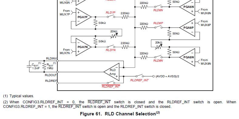
For reducing noise from the cables, caused by movements and capacitive coupling, it's necessary to use active shielding. Therefor I want to use the Right Leg Drive Signal by inserting the TLV2221 as shield driver. Unfortunately I don't understand the calculation of RLDOUT and RLDINV respectively (Figure 47, ADS1298 datasheet).

What happens after the PGAs and which influence have common-mode signals and difference signals? I can't find a logical relationship between INxP, INxN, RLDOUT and RLDINV.

Is the only task of the external elements (R=390k; C=10nF) to provide a low pass filter with RLD_AMP? And if so, I  miss an additional resistor at the 'inverting input' of RLD_AMP to calculate the properties of the filter (similar to an active low pass filter, realised by an operation amplifier).

Thank you for your help!

Norman

  • Hi Norman, 

    Any number of INxP and INxN inputs can be routed into the RLD amplifier's inverting input using the corresponding RLD_SENSP and RLD_SENSN registers. Each INxP and INxN passes through a PGA and 220k of impedance before connecting to the inverting input of the RLD amplifier. Please see Figure 61:

    The non-inverting input takes a DC reference input, equal to either mid-supply or some external reference voltage.

    The RC filter on the RLDOUT pin is used to low-pass filter the RLD output, as you correctly mentioned. The "missing resistor" you are referring to at the inverting RLD input would be some parallel combination of the 220k resistors shown above.

    Regards,

  • Hello Ryan,

    Thank you for your really helpful answer, I overlooked the 220k resistors, but now the appearance of RLDOUT and RLDIN is clear to me. But now I've got another questions:

    -The low-pass filter, composed of R_EXT and C_EXT, generally produce a phase shift. Why can you still use RLDOUT for Driven Right Leg or for Shield Drive? I think you need these signals in-phase with your INxP and INxN to suppress noise signals.

    -For the implementation of the Shield Drive, I want to feed back the common mode of my measured signals. However, by using RLDINV (after removing C_EXT and R_EXT) the common mode signal is overlain by the difference input. Is there any possibility to tap only the common mode signal of the input signals for the Shield Drive?

    Best Regards,

    Norman

  • It has become clear to me, why the RLDOUT signal needs to be out of phase for Driven Right Leg.

    The ADS1298ECGFE users guide describes in chapter 4.8.2. how to set the jumper J15 and J17 to get an in-phase or out-of-phase RLD signal. To get the in-phase RLD signal the jumper J17 must be set to 2-3, consequently RLDINV is connected to the TLV2221. Nevertheless the internal OpAmp 'RLD_AMP' and the external feedback (R8, C20) build an integrator what means that the input levels of the 'RLD_AMP' have to be the same. So is it not possible to use RLD_INV with the external feedback circuit?

    Does it make any sense to use Driven Right Leg and the Shield Driver simultaneously? Or has it the effect of overcompensation?