


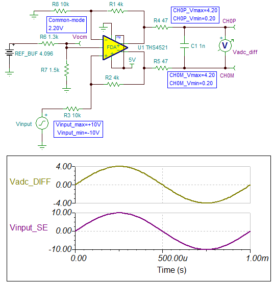
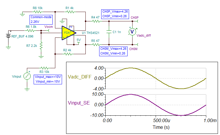
I am using ADS8284IB which is a 18 bit +- 2.5 LSB integral linearity ADC. With this ADC I am not getting +- 2.5 LSB accuracy. I have used some hardware to convert bipolar single ended signal in to true bipolar differential signal. This hardware uses two op-amps (OP07). To convert bipolar input signals to uni-polar differential signals I have used resistance network as suggested in the data sheet of ADS8284 ADC. I have used 1.2K resistance with 1% tolerance in the resistance network. The error I am getting is about 400 uV on +-4 volt range. The schematic diagram is attached as ADS8284_CH0.pdf.
Please suggest alternate solution for
(1) Bipolar single ended signal in to true bipolar differential signal. If some standard IC’s are available.
(2) Bipolar input signals to uni-polar differential signals in place of resistance network.
Please suggest solution to reduce the error in conversion.


