Hello,
I’m having issues interfacing with the AMC7812. It’s connected using an SPI interface with a MSP430G2553 CPU. The MSP430G2553 CPU is on a TI Launchpad MSP-EXP430G2 PCB, which is powered over USB but has been modified such that it uses 3.3 V rather than 3.6 V. The SPI_SCK, SPI_MOSI, SPI_MISO, SPI_NSS, RESET and GND of the TI Launchpad PCB are connected using a short cable (approximately 10 cm) to the PCB with the AMC7812 on it.
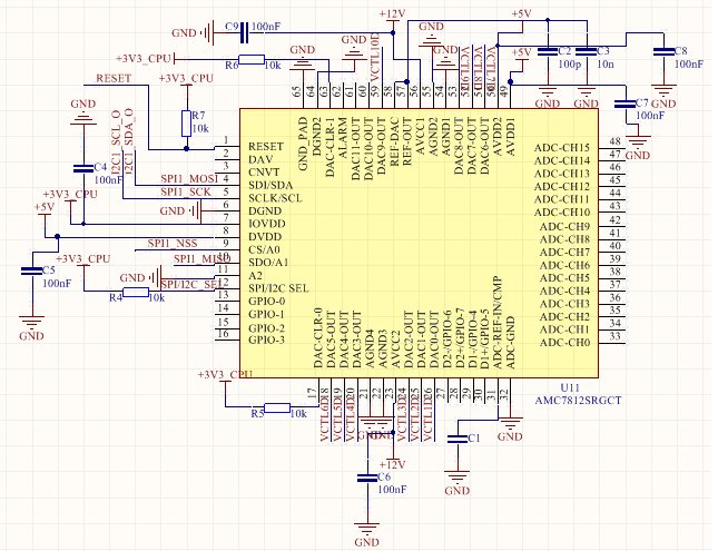
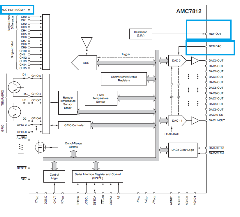
The schematic for the AMC7812 section of the circuit is as follows:
The code I am using on the MSP430G2553 CPU to control it is as follows:
/*
* main.c
*/
#include <msp430.h>
#include <msp430g2553.h>
#include <stdio.h>
unsigned char address_read;
unsigned char databyte1_read;
unsigned char databyte2_read;
void clockConfig()
{
// configure the CPU clock (MCLK)
// to run from DCO @ 16MHz and SMCLK = DCO / 4
BCSCTL1 = CALBC1_16MHZ; // Set DCO
DCOCTL = CALDCO_16MHZ;
BCSCTL2= DIVS_3 + DIVM_0; // divider=4 for SMCLK and 1 for MCLK
}
void pinConfig()
{
// set the pin mode 3 for pins 1, 2, 4 of port 1 (USCI mode)
P1SEL = BIT1 + BIT2 + BIT4; // low bit = 1 for pin 1, 2, 4
P1SEL2 = BIT1 + BIT2 + BIT4; // high bit = 1 for pin 1, 2, 4
P1DIR |= BIT3 + BIT5; // p1.3 and p1.5 set to output to drive RESET and CS
P1OUT |= BIT3 + BIT5; // pull p1.3 and p1.5 to high - RESET and CS high
}
// USCI
void spiConfig()
{
UCA0CTL0 |= UCMSB + UCMST + UCMODE_0 + UCSYNC;
// synchronous (=SPI) master 3 wire SPI, clock polarity low
/*SPI mode is selected when the UCSYNC bit is set and SPI
mode (3-pin or 4-pin) is selected with the UCMODEx bits, i.e.
slave enabled when UCxSTE pin is low.*/
//use SCLK : 4MHz
UCA0CTL1 |= UCSSEL_2;
// set baud rate = SMCLK, no further division
UCA0BR0 = 0;
UCA0BR1 = 0;
UCA0MCTL = 0; // No modulation
UCA0CTL1 &= ~UCSWRST; // **Initialize USCI **
}
// sets a register of the TI AMC7812 Multichannel ADC/DAC via SPI
void setRegisterValue(unsigned char address, unsigned char databyte1, unsigned char databyte2)
{
P1OUT &= (~BIT5); // Select Device
// __delay_cycles(10);
UCA0TXBUF = address; // Send address register byte
while (!(IFG2 & UCA0TXIFG)); // wait for TX buffer ready
UCA0TXBUF = databyte1; // Send data byte 1
while (!(IFG2 & UCA0TXIFG)); // wait for TX buffer ready
UCA0TXBUF = databyte2; // Send data byte 2
while (!(IFG2 & UCA0TXIFG)); // wait for TX buffer ready
__delay_cycles(70);
P1OUT |= (BIT5); // Unselect Device
__delay_cycles(146200);
}
void powerdacConfig()
{
__delay_cycles(400000);
P1OUT &= ~BIT3; // pull p1.3 to low - RESET low
__delay_cycles(400000);
P1OUT |= BIT3; // pull p1.3 to high - RESET high
__delay_cycles(400000);
setRegisterValue(0x6B, 0x3F, 0xF8); // Write to Power-down register - turn on Internal Reference and DACs 0-9
setRegisterValue(0xEB, 0x00, 0x00); // Read from Power-down register
setRegisterValue(0x59, 0x03, 0xFF); // Write to DAC gain register - set DAC 0-9 gain bits to 1
setRegisterValue(0x58, 0x03, 0xFF); // Write to DAC config register - enable sync. load for DACs 0-9
}
void loadData()
{
setRegisterValue(0xEC, 0x00, 0x00); // Read from device ID register
setRegisterValue(0x33, 0x08, 0x00); // Write to DAC 0 data register - set to 2048/4096 counts = 6 V
setRegisterValue(0xB3, 0x00, 0x00); // Read from DAC 0 data register - set to 2048/4096 counts = 6 V
setRegisterValue(0x34, 0x08, 0x00); // Write to DAC 1 data register - set to 2048/4096 counts = 6 V
setRegisterValue(0x35, 0x08, 0x00); // Write to DAC 2 data register - set to 2048/4096 counts = 6 V
setRegisterValue(0x36, 0x08, 0x00); // Write to DAC 3 data register - set to 2048/4096 counts = 6 V
setRegisterValue(0x37, 0x08, 0x00); // Write to DAC 4 data register - set to 2048/4096 counts = 6 V
setRegisterValue(0x38, 0x08, 0x00); // Write to DAC 5 data register - set to 2048/4096 counts = 6 V
setRegisterValue(0x39, 0x08, 0x00); // Write to DAC 6 data register - set to 2048/4096 counts = 6 V
setRegisterValue(0x3A, 0x08, 0x00); // Write to DAC 7 data register - set to 2048/4096 counts = 6 V
setRegisterValue(0x3B, 0x08, 0x00); // Write to DAC 8 data register - set to 2048/4096 counts = 6 V
setRegisterValue(0x3C, 0x08, 0x00); // Write to DAC 9 data register - set to 2048/4096 counts = 6 V
setRegisterValue(0x4C, 0x0C, 0x00); // Write to AMC config register - activate sync. load for DACs 0-9
__delay_cycles(14600000);
}
int main(void) {
// setup
WDTCTL = WDTPW | WDTHOLD;
clockConfig();
pinConfig();
spiConfig();
int i=0;
while(1)
{
//__delay_cycles(14600000);
powerdacConfig();
loadData();
if ( i == 0 ) break; // for an example.
i++;
}
while(1)
{
//__delay_cycles(73000000);
loadData();
//if ( i == 0 ) break; // for an example.
//i++;
}
}
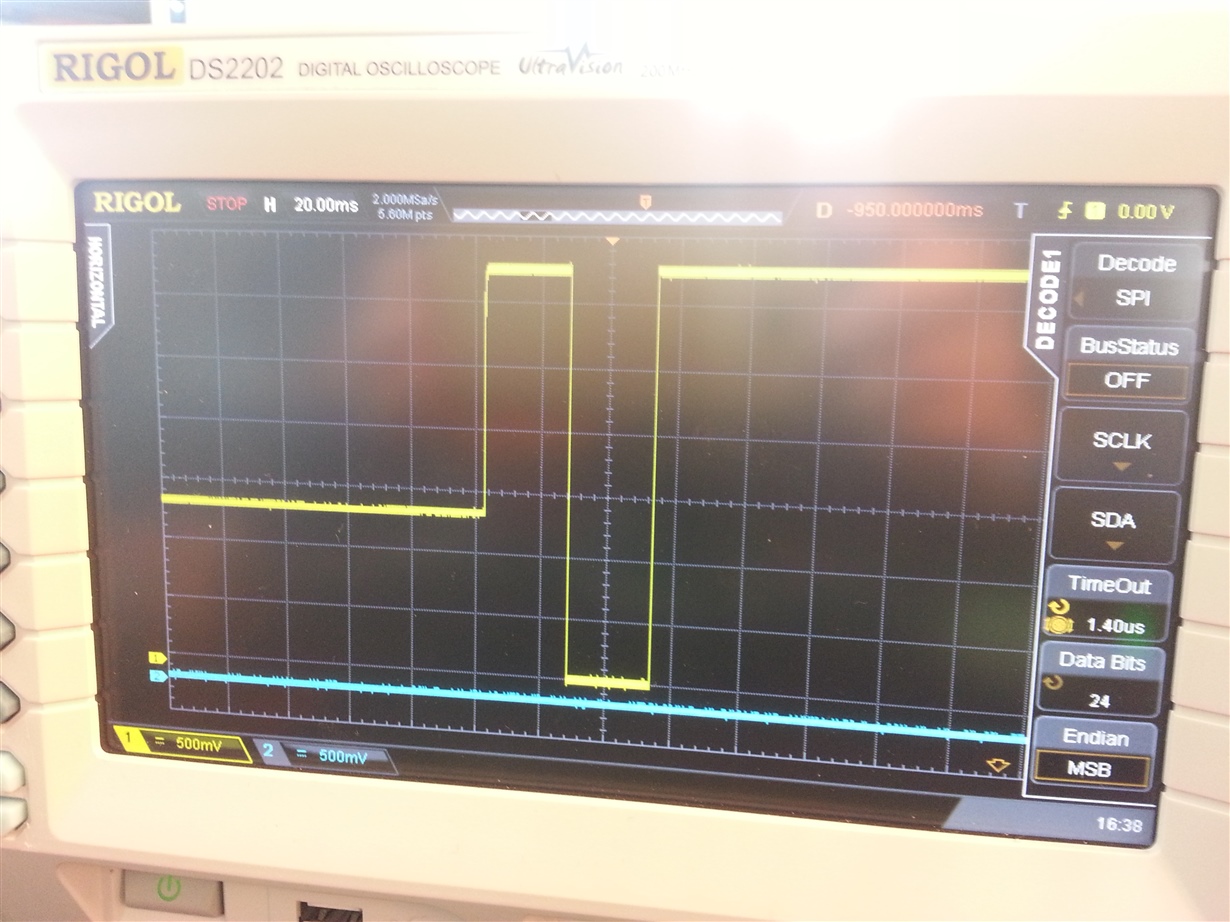
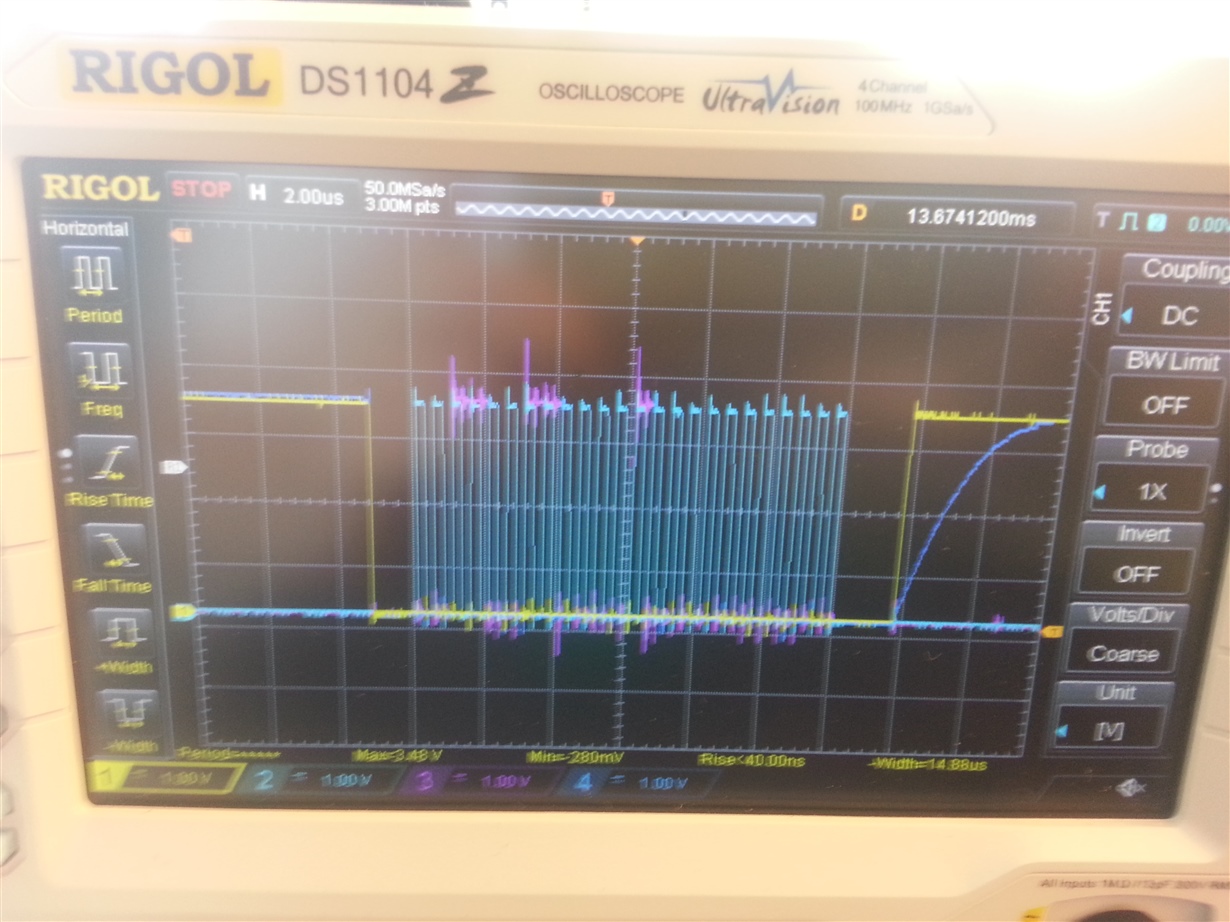
As you can see the RESET pin is high at power-up and is then pulled low after 27 mS before being pulled high again after a further 27 mS. Then there is a 27 mS delay before I start writing to or reading from registers on the AMC7812. Firstly I write to the power-down register, to activate the internal reference and DACs 0-9, then I try to read the device ID, then I write to the DAC gain and configuration registers. There is then an infinite loop, with approximately 1 second delay between each cycle, whereby I try to read the device ID register first and then load data into DACs 0-9 and synchronously update it using the AMC configuration register.
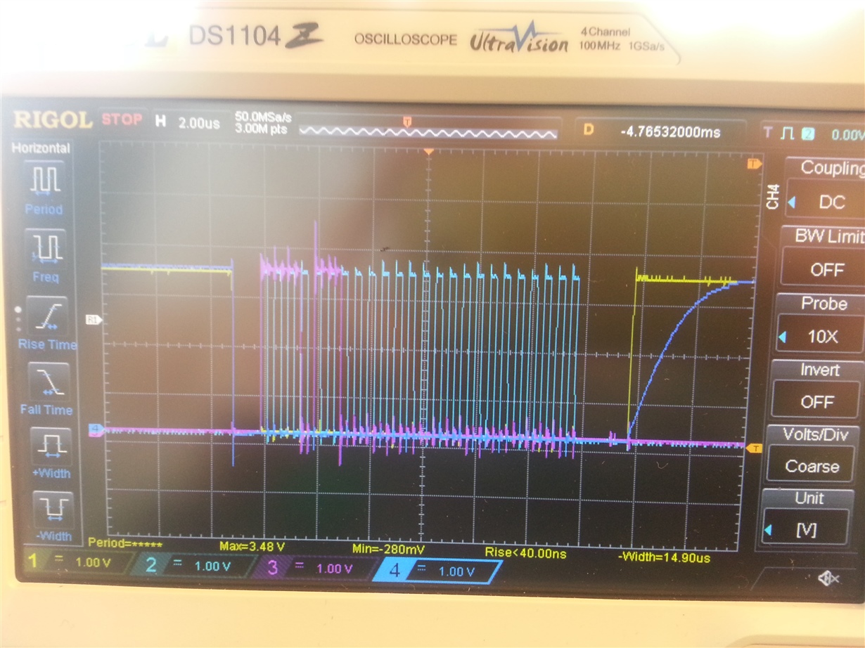
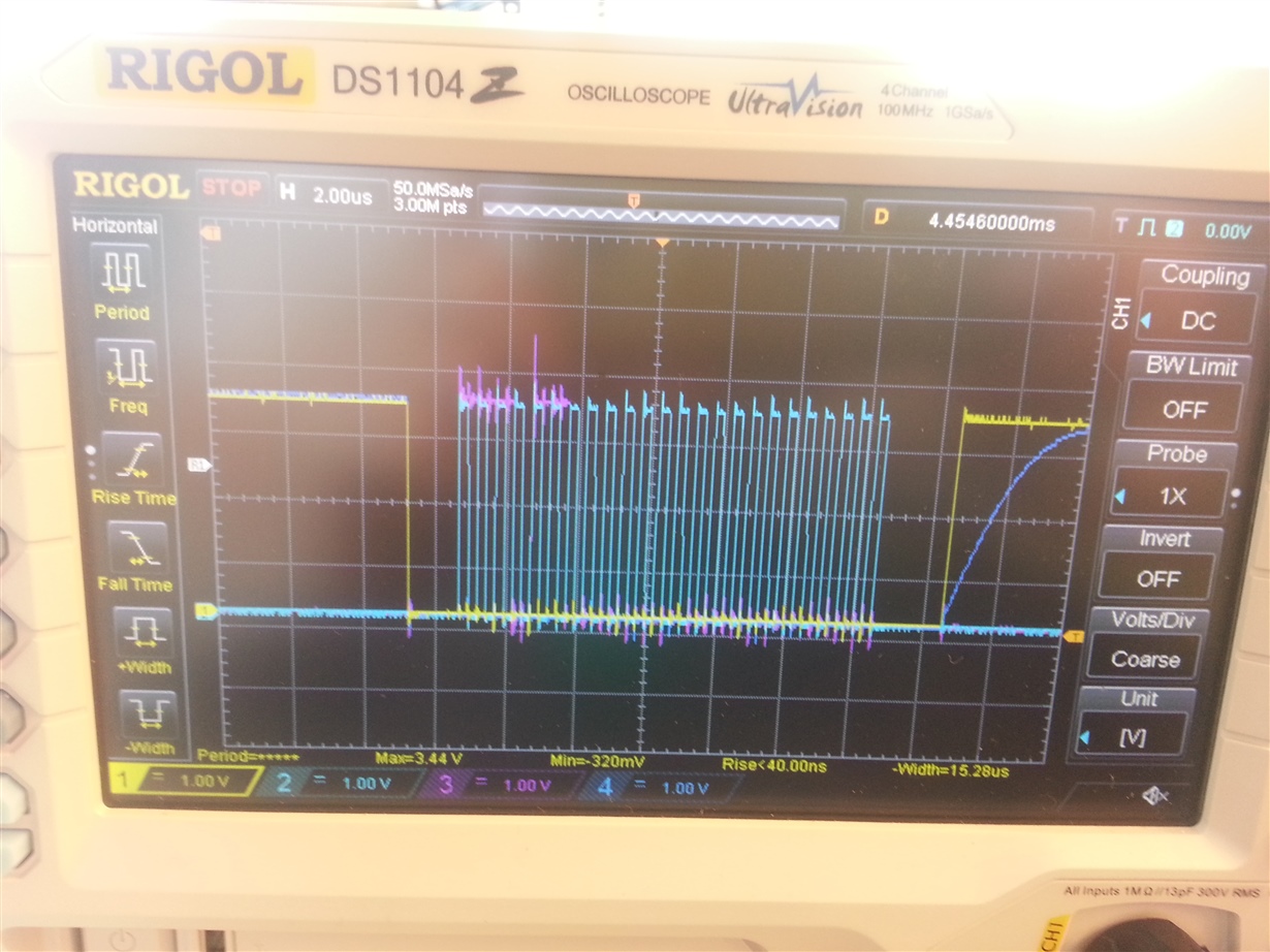
The problem is that I can’t read the device ID and the internal reference and DAC 0-9 outputs are all at 0 V. I’ve taken screenshots below using the oscilloscope of what is happening when I try to read the device ID:
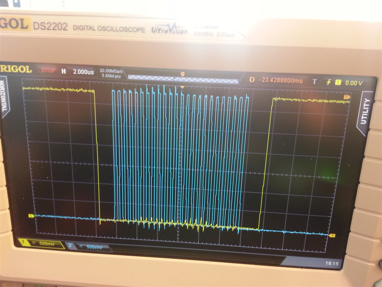
- SPI_NSS, SPI_SCK – exactly 24 clock cycles occur between when the chip select is pulled low and when it goes high again. I am using a 4 MHz clock for the SPI. There is more than adequate delay between when chip select goes low and the clock starting and also between when the clock ends and when chip select goes high.
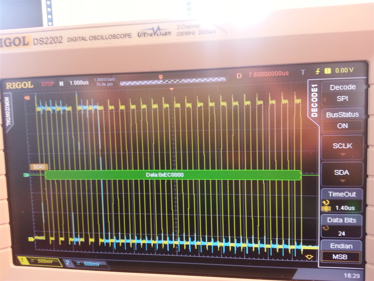
2. SPI_SCK, SPI_MOSI – as you can see the oscilloscope’s SPI decode function is able to decode the transmission successfully, i.e. 0xEC 0x00 0x00.
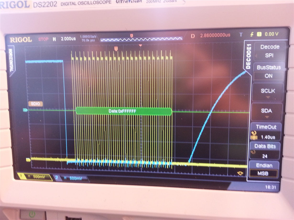
3. SPI_SCK, SPI_MISO – this is taken from the CS-active period after the above one, i.e. when the AMC7812 should output the device ID from the 0x6C register. The MISO line is pulled low but then stays low for the duration of the CS-active period.
I have also taken a screenshot using the oscilloscope of what happens to the RESET pin at startup, as you can see it starts off at a floating voltage of approximately 1.3 V (as the MSP430G2553 is powered up after the AMC7812 voltage rails), then within 27 mS of power-on it is pulled low for 27 mS before being pulled high again:
I have arranged for the AMC7812 IC to be replaced on our PCB, to see if it has been damaged in some way or if it’s not fitted correctly on the PCB. The pin 1 marker is in the right location and as far as I can tell all the pins of the IC are connected to the pads on the PCB. You help would be much appreciated!


