This thread has been locked.

If you have a related question, please click the "Ask a related question" button in the top right corner. The newly created question will be automatically linked to this question.

SPI communication for the ADS1298

Other Parts Discussed in Thread: ADS1298

Hello, I am using the evaluation board of the ads1298 and I'm trying to make the spi communication between the board and an arduino due.

As a start, I'm trying to read the ID but the DRDY is always 1.

In the start of the communication I send a RESET command, then a SDATAC  and then I'm trying to read the ID.

The clock frequency I use is 1MHz.

Here is the code

#include "SPI.h"

int CS=10;
int RESET=0x06;
int RDATAC=0x10;
int SDATAC=0x11;
int START=4;
int data;


void setup() {
  SPI.begin(CS);
  SPI.setDataMode(CS, SPI_MODE1);
  SPI.setBitOrder(CS, MSBFIRST);
  SPI.setClockDivider(CS, 84); 

}

void loop() {
  digitalWrite(START,HIGH);
  SPI.transfer(CS,RESET);
  SPI.transfer(CS,SDATAC);
  while(1){
    SPI.transfer(CS,B00100000);
    SPI.transfer(CS,1);
    delayMicroseconds(2);
    data=SPI.transfer(CS,0);
  }
}

Here I attached the plots from a logic analyzer.

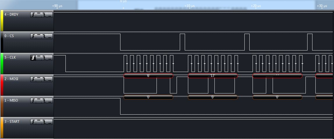
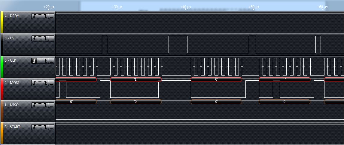
I am very confused as I do what the datasheet says.

  • Hey DBour,

    There are a couple of issues that I can see. First, you need to wait at least 18 ADS1298 master clock periods after issuing a reset command before communicating with the device again. This is the case because resetting the device resets all of the analog electronics in addition to resetting the digital electronics. Second, you must wait at least 4 ADS1298 master clock periods after issuing an SDATAC command before communicating. This is so the device has time to decode and execute the command. Finally, you need to keep Chip Select low for the entirety of the RREG command. Right now your routine pulses CS every 8 bits which will reset the interface each time and keep the device from decoding the RREG command or any of the address/number parameters.

    Looking briefly at your code, it looks like you pull the START pin high which should keep the modulator running constantly when the device is powered on. This means that the DRDY pin should always be pulsing at the data rate. If that is not the case, first check that the START pin is actually high by probing it near the actual device. If it is, check the power supply pins to make sure that everything is powered.

    Regards,
    Brian Pisani
  • In my previous code I had forgotten to define DRDY as input and START as output. Now I did that and I added the necessary delays but I still take the same output.
    What should I do to see the DRDY pulsing as a debugging process?
  • Hey DBour,

    You can probe the pin with the logic analyzer or oscilloscope to see if the negative edges occur at the data rate. If they do, then the device is likely powered correctly.

    Regards,
    Brian Pisani
  • I tested it with both an oscilloscope and a logic analyzer and the DRDY stays positive at 3.3v. When should I see it pulsing?
  • Hey DBour,

    If the START pin is held high constantly then DRDY should fall low at the data rate. Is the START pin high?

    Regards,
    Brian
  • Yes, I have it high constantly.

    I'm measuring the voltage in the test points and I  see that I have 4.713 in TP7 and 3.226 in TP10.

  • Hey DBour,

    TP10 is not directly connected to AVDD. If you are using bipolar supplies, you'll want to check both TP13 and TP6 to ensure they are both 2.5 V and -2.5V respectively. If you're using the unipolar supply, you'll want to check TP5 and ensure it is near 3 V.

    Brian Pisani
  • TP5 has 3.022

  • Hey DBour,

    If you've probed the START pin and it is also 3.3 V, then please probe all of the VCAP pins on the ADS1298.

    Brian
  • VCAP1: -1.318V
    VCAP2: 0.014V
    VCAP3: 1.268V
    VCAP4: -2.490V
  • Hey DBour,

    Those are definitely not the right voltages. Try probing the all the power supply pins right be the pins themselves rather than at the test points. The different AVDD/AVSS and the different DVDD pins power different parts of the device so its important to probe all of them. It's likely that 1) something isn't powered correctly or 2) the device suffered damage from an electrostatic event.

    Regards,
    Brian Pisani