This thread has been locked.

If you have a related question, please click the "Ask a related question" button in the top right corner. The newly created question will be automatically linked to this question.

AFE4490 not driving LEDs

Other Parts Discussed in Thread: AFE4490, CC2541, ADS1293, CC2640

Hi,

I am trying to interface AFE4490 for pulse oximetry by designing a custom board. The AFE4490 is not being able to generate any signal on TXN and TXP pins.

I have set all supply voltages as 3.3 V.

The voltages on various pins are as follows:

BG = 0.98 V

TX-REF = 0.68 V

VCM = 0.97 V

TXN = 2.52 V

TXP = 3.3 V

I am being able to see the signals on MOSI and MISO pins when I try to write and read registers. Also, the CLK_OUT of 4 MHz is being observed from the AFE4490. But, there is no signal on the ADC_READY pin.

Please help! 

Thanks in advance.

  • Puja,


    I'm moving this post to the Medical Forum where the AFE4490 is supported. I'm sure you'll get an answer here.


    Joseph Wu
  • Hi Puja,

    What are you writing to the AFE, and what are you reading back from the AFE? Could I also see the schematic for the custom board?

    Best Regards,
    Lakeishia
  • Hi Lakeishia,

    Thanks for the quick response!
    I am currently writing one byte, i.e., 0x0000aa to register 0x01 and reading back the same register, obtaining 'aa' on the MISO line.
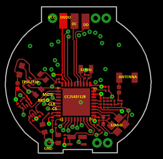
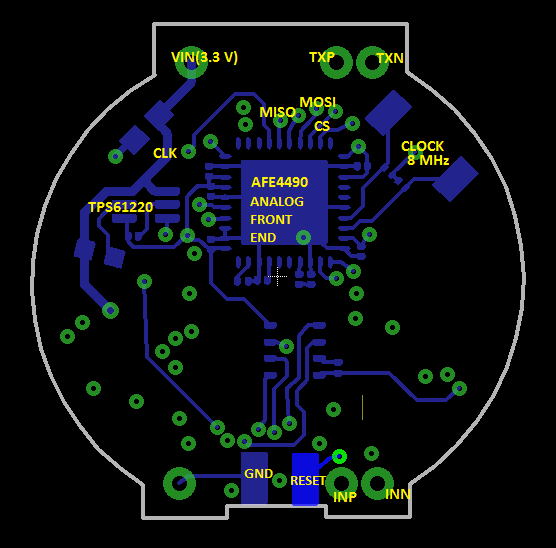
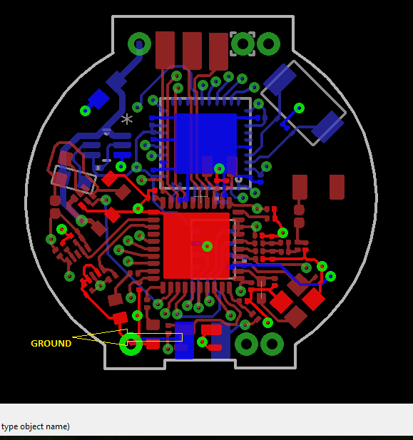
    I am including the schematic for AFE4490 and the layer of my custom board containing it. I have used CC2541 as the main SOC in my design. The PCB consists of four layers.

    pulsev6 copy_afe.pdf

    This is the schematic for AFE4490.

    Following are the images of the custom board:

     Top layer with CC2541

     Bottom layer with AFE4490

    Following are the register settings that I am doing:

    void TI_ADS1293_WriteRegSettings(void)
    {

    TI_ADS1293_SPIWriteReg(0x01,0x003ae8); //// start of the sample LED2 signal with respect to the pulse repetition period (PRP)
    TI_ADS1293_SPIWriteReg(0x02,0x004e1e); //// end of the sample LED2 signal with respect to the pulse repetition period (PRP)
    TI_ADS1293_SPIWriteReg(0x03,0x003a98); //// start of the LED2 with respect to the PRP
    TI_ADS1293_SPIWriteReg(0x04,0x004e1F); //// TI_ADS1293_SPIWriteReg(0x04,0x001F3F); 4e1F end of the LED2 with respect to the PRP
    TI_ADS1293_SPIWriteReg(0x05,0x000050); //// start of the sample ambient LED2 signal with respect to the PRP
    TI_ADS1293_SPIWriteReg(0x06,0x001386); //// end of the sample ambient LED2 signal with respect to the PRP,
    TI_ADS1293_SPIWriteReg(0x07,0x0013d8); //// start of the sample LED1 signal with respect to the PRP
    TI_ADS1293_SPIWriteReg(0x08,0x00270e); //// end of the sample LED1 signal with respect to the PRP
    TI_ADS1293_SPIWriteReg(0x09,0x001388); //// start of the LED1 signal with respect to the PRP
    TI_ADS1293_SPIWriteReg(0x0A,0x00270f); //// TI_ADS1293_SPIWriteReg(0x0A,0x000F9F); 270f end of the LED1 signal with respect to the PRP
    TI_ADS1293_SPIWriteReg(0x0B,0x002760); //// start of the sample ambient LED1 signal with respect to the PRP
    TI_ADS1293_SPIWriteReg(0x0C,0x003a96); //// end of the sample ambient LED1 signal with respect to the PRP
    TI_ADS1293_SPIWriteReg(0x0D,0x000006); //// start of the LED2 conversion signal with respect to the PRP
    TI_ADS1293_SPIWriteReg(0x0E,0x001387); //// end of the LED2 conversion signal with respect to the PRP
    TI_ADS1293_SPIWriteReg(0x0F,0x00138e); //// start of the LED2 ambient conversion signal with respect to the PRP
    TI_ADS1293_SPIWriteReg(0x10,0x00270f); //// end of the LED2 ambient conversion signal with respect to the PRP
    TI_ADS1293_SPIWriteReg(0x11,0x002716); //// start of the LED1 conversion signal with respect to the PRP
    TI_ADS1293_SPIWriteReg(0x12,0x003a97); //// end of the LED1 conversion signal with respect to the PRP
    TI_ADS1293_SPIWriteReg(0x13,0x003a9e); //// start of the LED1 ambient conversion signal with respect to the PRP
    TI_ADS1293_SPIWriteReg(0x14,0x004e1f); //// end of the LED1 ambient conversion signal with respect to the PRP
    TI_ADS1293_SPIWriteReg(0x15,0x000000); //// start of the ADC reset0 conversion signal
    TI_ADS1293_SPIWriteReg(0x16,0x000005); //// end of the ADC reset0 conversion signal
    TI_ADS1293_SPIWriteReg(0x17,0x001388); //// start of the ADC reset1 conversion.
    TI_ADS1293_SPIWriteReg(0x18,0x00138d); //// end of the ADC reset1 conversion.
    TI_ADS1293_SPIWriteReg(0x19,0x002710); //// start of the ADC reset2 conversion.
    TI_ADS1293_SPIWriteReg(0x1A,0x002715); //// end of the ADC reset2 conversion.
    TI_ADS1293_SPIWriteReg(0x1B,0x003a98); //// start of the ADC reset3 conversion.
    TI_ADS1293_SPIWriteReg(0x1C,0x003a9d); //// end of the ADC reset3 conversion.
    TI_ADS1293_SPIWriteReg(0x1D,19999); //// The contents of this register can be used to set the pulse repetition period (PRP)(in number of clock cycles of the 4-MHz clock).
    TI_ADS1293_SPIWriteReg(0x1E,0x000101); //// This register configures the clock alarm pin, timer, and number of averages.
    TI_ADS1293_SPIWriteReg(0x1F,0x000000); //// This register is a spare register and is reserved for future use.
    TI_ADS1293_SPIWriteReg(0x20,0x000000); //// This register sets the device transimpedance amplifier gain mode and feedback resistor and capacitor values.
    TI_ADS1293_SPIWriteReg(0x21,0x000000); //// This register configures the ambient light cancellation amplifier gain, cancellation current, and filter corner frequency.
    TI_ADS1293_SPIWriteReg(0x22,0x011f08); //// This register sets the LED current range and the LED1 and LED2 drive current.
    TI_ADS1293_SPIWriteReg(0x23,0x020000); //// This register controls the LED transmitter, crystal, and the AFE, transmitter, and receiver power modes.
    TI_ADS1293_SPIWriteReg(0x24,0x000000); //// This register is a spare register and is reserved for future use.
    TI_ADS1293_SPIWriteReg(0x25,0x000000); //// This register is a spare register and is reserved for future use.
    TI_ADS1293_SPIWriteReg(0x26,0x000000); //// This register is a spare register and is reserved for future use.
    TI_ADS1293_SPIWriteReg(0x27,0x000000); //// This register is reserved for factory use. Readback values vary between devices.
    TI_ADS1293_SPIWriteReg(0x28,0x000000); //// This register is reserved for factory use. Readback values vary between devices.
    TI_ADS1293_SPIWriteReg(0x29,0x000000); //// This register controls the Alarm pin functionality
    TI_ADS1293_SPIWriteReg(0x2A,0x000000); //// This register contains the digital value of the latest LED2 sample converted by the ADC. The ADC_RDY signal goes high each time that the contents of this register are updated
    TI_ADS1293_SPIWriteReg(0x2B,0x000000); //// This register contains the digital value of the latest LED2 ambient sample converted by the ADC. The ADC_RDY signal goes high each time that the contents of this register are updated
    TI_ADS1293_SPIWriteReg(0x2C,0x000000); //// This register contains the digital value of the latest LED1 sample converted by the ADC. The ADC_RDY signal goes high each time that the contents of this register are updated
    TI_ADS1293_SPIWriteReg(0x2D,0x000000); //// This register contains the digital value of the latest LED1 ambient sample converted by the ADC. The ADC_RDY signal goes high each time that the contents of this register are updated
    TI_ADS1293_SPIWriteReg(0x2E,0x000000); //// This register contains the digital value of the LED2 sample after the LED2 ambient is subtracted
    TI_ADS1293_SPIWriteReg(0x2F,0x000000); //// This register contains the digital value of the LED1 sample after the LED1 ambient is subtracted
    TI_ADS1293_SPIWriteReg(0x30,0x000000); //// This register is read only. This register contains the status of all diagnostic flags at the end of the diagnostics sequence

    ///// Led 2 is RED and LED in IR

    delaym(10);
    }

  • Hi Puja,

    After programming the registers, do the LEDs turn on? If not, could you please send what you are reading back from the AFE? 

    Best Regards,

    Lakeishia

  • Hi Lakeishia,

    I am facing a strange problem now. The LEDs did light up finally, but after a few iterations of testing, they again got switched off. I am not being able to figure out the reason.

    Regards,
    Puja
  • Hi Every one,

    I am Madhusudan, i was working on AFE4490 IC for Pulse oxymeter which will interface with the TI CC2640 controller,

    i am facing the issue with perfusion, when the device subjected for thin and a white finger(high perfusion) signal is getting saturated(1.2V), i tried changing the intensity and then changed the gain also but still it is getting saturated, i need help on this,

  • Hi Madhusudan,

    What the LED current set for both the LEDs?
    Also what is the gain?

    Regards,
    Prabin
  • Hi Prabin,

    I have set current for IR = 62mA and Red = 72mA,
    Gain = cf = 10pf and rf = 500kohm,

    when I checked with the eastern countries i am not getting any signal out, it is getting saturated
  • Hi Madhusudan,

    Signal received by the devices greatly depends on skin tone as seen by you.

    To avoid the saturation you can either reduce the LED currents or RF.

    Regards,

    Prabin