This thread has been locked.

If you have a related question, please click the "Ask a related question" button in the top right corner. The newly created question will be automatically linked to this question.

DAC102S085: DAC102S085

Part Number: DAC102S085

HI,

We have an existing issue with one of your DAC's in our design. Here is how it goes:
 
DESIGN:

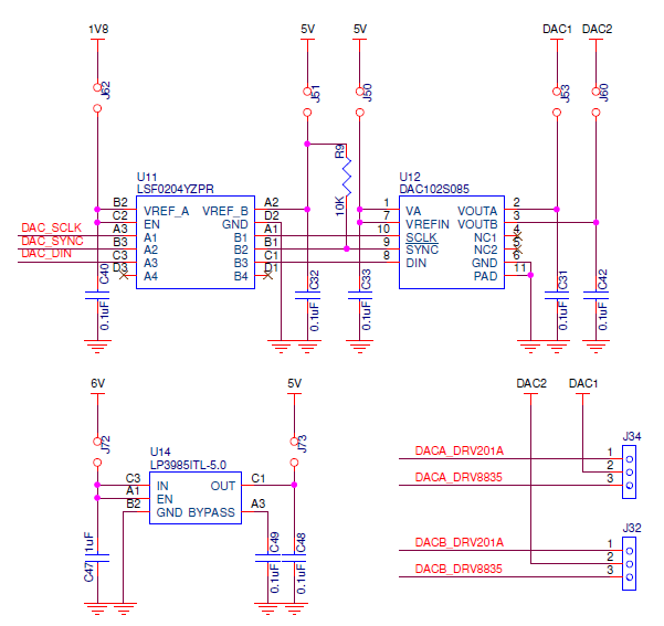
  • C48 - Changed to 1uF.
  • C31, C42 - Changed to 1500pF
ISSUE:
  • J72, J73, J62, J51, J50 - Shunt Jumpers ON
  • J53, J60, J34, J32 - Shunt Jumpers OFF
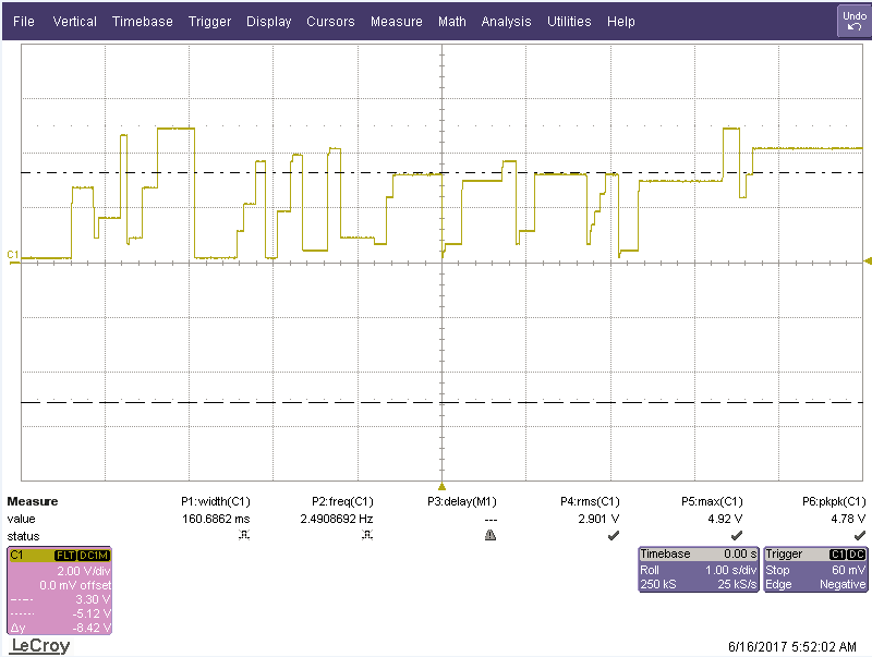
  • Under this condition the O/P at J73 in this particular board is 5.010V. We see the following on J53 & J60 on the chipside:

  • However if we remove the jumper J73 and feed a voltage between 4.950 - 5.005V on the 5V side, we see the following:

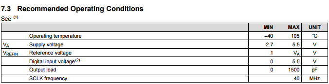
  • DAC I/P voltage range according to datasheet:

We would like to know what is going wrong here. 

  • Hi Shyam,

    Do you see the issue only on one board or is it across boards? From your explanation it looks more like the LDO issue and not of the DAC. If you see it only on one board, then either there is a device problem or component assembly problem. However, if you see it across boards, you need to check with the LDO forum - they should be able to help you.

    Regards,
    Uttam Sahu
    Applications Engineer, Precision DACs
  • Hi Uttam,

    Here is what we tried:

    • We tried this on multiple boards and observing the same issue with the DAC.
    • We wanted to take the LDO out of the eqation, so we are powering the DAC directly at J73 5V side. DAC works good till ~4V9 and shows wierd behaviour like the scopeshot below after 4V9, however as mentioned above, based on the datasheet, DAC was suppossed to work properly till 5V5:

    Further, we would like to close this issue ASAP, as this is blocking our production timeline. So it would be great if we can resolve this at the earliest. We can share you a board if that might help. 

  • Hi Uttam,

    Also would like to mention that the DAC chip works good on the lower voltage levels till 1V8.
  • Hi Shyam,

    When you say 4.9V or 1.8V, do you mean that you supply these voltages in place of 5V? Or is it the output voltage you are looking for?

    Regards,
    Uttam
  • Hi Uttam,

    Sorry about the confusion, when we externally give voltage between 1V8 - 4V9, the DAC works.

  • Hi Shyam,

    This looks strange. If you are providing the VDD from a regulated source, could you please monitor the current when you go beyond 4V9? If that looks fine, please order few fresh DAC samples and test with them.

    Regards,
    Uttam
  • Hi Uttam,

    We got fresh samples from Ti and we are still seeing the same. This issue has been open for more than a month now. Please do let us know how we can resolve this at the earliest. We can give youa board to debug, if that helps. 

  • Hi Shyam,

    Could you check the SPI communication pins during these tests with an oscilloscope and post the results?  I am wondering if there is some issue with the translator causing the data to be incorrectly latched.  

    Also, you have 0.1µF capacitors on the outputs of the DAC, while the maximum load capacitance of this device is specified at 1500pF.  I wonder if the output is oscillating and possibly causing issues.  Please try removing the capacitors and seeing if the performance changes.

    Thanks,

    Paul

  • Hi Uttam,

    Both the O/P caps are removed. Will send you the scope shots soon.
  • Hi Shyam,

    Is there any update on the scope shots?

    Regards,
    Uttam
  • Hi Uttam,

    Here are the scope shots:

    u75-output23.tif

    u75-output24.tif

    u75-output25.tif

    u75-output26.tif

    u75-output27.tif

    u75-output28.tif

    u75-output29.tif

    u75-output29.tif

    u75-output30.tif

    u75-output31.tif

    u75-output32.tif

    u75-output33.tif

    u75-output34.tif

    Here are locations where the scope shots were taken in the schematic:

    • DAC-SCLK: J63
    • DAC-SYNC: J64
    • DAC-DIN: J68
    • DAC-OUT2: J60


  • Hi Shyam,

    Thanks for the shots. I am looking into them. Will get back ASAP.

    Regards,
    Uttam
  • Hi Shyam,

    I don't see the waveform when the output is problematic. The DAC output looks fine in my opinion. Could you tag the waveforms for better understanding if I am missing something? Another point is that in the DIN packet you are selecting DACA. However, you are monitoring DACB. Could you please clarify? I also couldn't correlate any power supply change to any waveform. Please try to tag them properly.

    Regards,
    Uttam
  • Hi Uttam,

    Shyam is my colleague - he is the EE on this project, and I am the system architect.  Permit me to interject on his behalf.

    ( Thanks a lot for your help - I trust we can root cause this issue with some concerted effort).

    Please look at image U75-output24.tif, below.

    1)The red line is the output of DAC2.  ( I believe your observation about the DACA vs DACB is incorrect - the code is such that we first write to dac1( without updating the output), then write to dac2( with update of both outputs).  Page 16 of the user manual ). 

    2) DAC1 and DAC2 are both driven with a sawtooth waveform, offset in phase by 90 degrees.

    do {
            for( i = 0 ; i < 1024; i+=50) {
                   spi_slave_select(spi_dev,1);
                   do_dac_blah(spi_dev,i,(i+511));
                   k_sleep(10); //Yield for 10 ms
             }
    } while(1);

    3) The expectation is that the sawtooth value ( i.e output of DAC1 and DAC2) changes FOR EVERY invocation of do_dac_blah(...). 

    4) For a voltage level under 5V, we see a nice ramp that updates at each (pair of) writes, as expected. At voltages above 5V, that ramp is no longer smooth - i.e., there are missing updates. NOTE THAT THERE IS NO CHANGE IN CODE OR HARDWARE BETWEEN THESE TWO EXPERIMENTS - the only change in the voltage being fed into the chip, as well as the IO voltages.

    5) Note that our schematic is slightly complicated ( by the fact that we drop a 6V to 5V, and then convert the microprocessor's SPI IOs to the same 5V). I am not certain if that could explain this behavior, but I am mentioning it so you take note of the fact.

    Please let me know if this helps explain the problem. 

    Thanks

    Manu

  • Hi Manu,

    My apologies for keeping this issue pending for so long. I am looking into your latest post. In the meanwhile I am coordinating with the FAE to figure out a better way to debug the issue. Will let you know the progress soon.

    Regards,
    Uttam