This thread has been locked.

If you have a related question, please click the "Ask a related question" button in the top right corner. The newly created question will be automatically linked to this question.

ADS1292: SPI Communication Problem???

Part Number: ADS1292
Other Parts Discussed in Thread: ADS1298, ADS1299, ADS1294,

Dear my colleagues

I am making 2-channel EEG device with ADS1292IPBS.

Actually, our team have been made EEG device with ADS1294, ADS1298, and ADS1299 already.

So I started to design the circuit and firmware code.

I would like to explain my test set-up first.

My EEG device adapted 8-bit MCU, ATMEGA168 and ADS1292IPBS.

MCU communicates with the labview software on the host PC via UART communication.

At the beginning of the firmware, I initialized SPI communication, set up ADS1292 registers, and then UART communication.

UART communication between MCU and host PC was OK.

Then, I tried to verify SPI communication.

So I modified CONFIG2 register on ADS1292 in order to generate the internal test signal on the both channels with the frequency of 1Hz.

Our data sampling rate is 250Hz. (Datasheet says that default value is 500Hz.)

However, test signal seems not to be generated correctly. 

I turned on the device and operated the labview user software to collect the test signals

Unfortunately, it is hardly to get the intended signal (square-wave test signal)

In most cases, ADS1292 does not generate the test signals. It just gives out noise-like signals randomly.

What's more, sometimes, signals with default sampling rate was generated... (I did not change the sampling rate at all)

If I turned the device and tried the operation again, the correct signal sometimes appears....but not many times....

Firmware did not change...

I just turn off / on the device but ADS1292 on my EEG device works differently.

I doubted that registers of the IC were not initialized or defined correctly on in a large percentage of cases, but I am not sure.

I want to know the root cause of this malfunction.

I reviewed the datasheet many times and I did not find any mistakes on the code (I was confident with my ADS1292 settings at first.)

But the problem still remains and I am struggling to find the solution... very difficult!!!

Could you please give me some useful advice??

How can I fix this phenomenon??

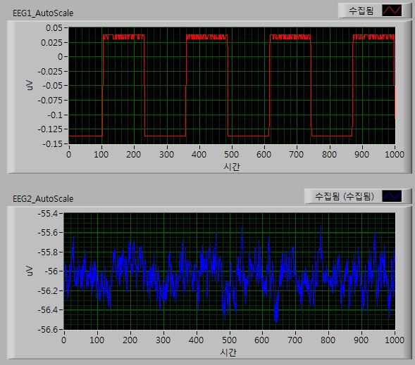
For your understanding of my problem, please check the attached picture...

It shows the measured 2-channel square-wave test signals.

Unfortunately, the second channel does not work properly despite the same set-up with the first channel...

(At this time, channel 1 works well with the right sampling rate, 250Hz. Number 1000 on x-axis means the 1000th points.

Graph shows 4-second measurements with the exact frequency.)

I am waiting for your help.

Thanks :)

  • Hello Heejin,

    Thanks for your post!

    To start, can you please share the complete register settings that you read back from the device after programming? We should confirm that the settings match what you intended to write and that they are correct to set up the internal test signal.

    Also, the amplitude of your test signal should be much larger. I believe this is likely a simple miscalculation or scaling error.

    Best Regards,

  • Hello, Andrews

    I am glad to see your reply.
    I will describe the complete register settings for ADS1292 here.

    -------------------------------------------------------------------------------------------------------------------------------------------------------
    [A] initialize ADS1292...

    - Initial flow
    1) CLKSEL = high for the use of internal clock, then wait for 10ms to wait oscillator wake up
    2) RESET = high, then wait for 1s for power-on reset
    3) CS = low
    4) RESET = low to issue reset pulse, then wait for 1ms (18tclk)
    5) RESET = high to end reset pulse, then wait for 1ms (18tclk)
    6) SPDR = SDATAC (SPDR: SPI data register)
    7) CS = high

    [B] ADS1292 Register Setting

    1) CS = low to start SPI communication
    2) Specific Settings below

    SPDR = 0b01000001; while(!(SPSR & 0x80)); // Write Register with start address 01h(config1)
    SPDR = 0b00000001; while(!(SPSR & 0x80)); // number of registers to be written: 2 (CONFIG1, 2)
    SPDR = 0b00000001; while(!(SPSR & 0x80)); // CONFIG1
    SPDR = 0b10100000; while(!(SPSR & 0x80)); // CONFIG2

    SPDR = 0b01000100; while(!(SPSR & 0x80)); // Write Registers with start address 04h(ch1set)
    SPDR = 0b00000001; while(!(SPSR & 0x80)); // number of registers to be written: 2 (CH1SET, CH2SET)
    SPDR = 0b01100000; while(!(SPSR & 0x80)); // CH1SET
    SPDR = 0b01100000; while(!(SPSR & 0x80)); // CH2SET

    3) Delay for 1ms
    4) CS = high to stop SPI communication

    [C] Settings for Test Signal

    1) CS = low to start SPI communication
    2) Specific Settings below

    SPDR = 0b01000010; while(!(SPSR & 0x80)); // Write Register with start address 02h(config2)
    SPDR = 0b00000000; while(!(SPSR & 0x80)); // number of registers to be written: 1
    SPDR = 0b10100011; while(!(SPSR & 0x80)); // CONFIG2 -> Square wave at 1Hz, +/-1mV amplitude

    SPDR = 0b01000100; while(!(SPSR & 0x80)); // Write Registers with start address 04h(ch1set)
    SPDR = 0b00000001; while(!(SPSR & 0x80)); // number of registers to be written: 2 (input value : 1)

    SPDR = 0b00010101; while(!(SPSR & 0x80)); // CH1SET
    SPDR = 0b00010101; while(!(SPSR & 0x80)); // CH2SET

    3) Delay for 1ms
    4) CS = high to stop SPI communication

    -------------------------------------------------------------------------------------------------------------------------------------------------------

    Thanks :)

  • Hello Heejin,

    Thanks for providing the register settings.

    It would be good practice to read all the registers before your test to confirm that the settings are written to the device correctly. This includes the ID register, which can tell us if the device has powered up correctly or not.

    I do not see any issue with the settings you are writing to the device. Are you enabling RDATAC mode again after writing the register settings? Or do you prefer to send the RDATA command each time you need to read data?

    Another option to consider is whether this could be a communication issue. Do you have access to a logic analyzer to see the data on DOUT? Perhaps there is a problem with the SPI timing which prevents you from reading the data on Channel 2. If possible, please look at /CS, SCLK, DRDY, and DOUT while capturing data.

    Best Regards,
  • Hello, Andrews

    Thank you for your kind assistance.

    Actually, the problem seems to be fixed.

    I inserted the 1-milli-second delay after each command and test signals were measured on both channels correctly.

    Codes below show the solution.

    ------------------------------------------------------------------------------------------------------------------------------------------------------------ 

    SPDR = 0b01000010; while(!(SPSR & 0x80)); // Write Register with start address 02h(config2)

    delay_ms(1); // 1ms delay..

    SPDR = 0b00000000; while(!(SPSR & 0x80)); // number of registers to be written: 1 

    delay_ms(1); // 1ms delay..

    SPDR = 0b10100011; while(!(SPSR & 0x80)); // CONFIG2 -> Square wave at 1Hz, +/-1mV amplitude 

    delay_ms(1); // 1ms delay..

    ------------------------------------------------------------------------------------------------------------------------------------------------------------ 

    I am afraid that registers were not written properly, maybe, due to the lack of sufficient time for applying new commands

    I did not check /CS, SCLK, DRDY, and DOUT yet which you recommended because I do not have a logic analyzer.

    But, I am going to operate the test-signal function repeatedly to confirm weather the problem appears again or not.

    Thanks :)