A related question is a question created from another question. When the related question is created, it will be automatically linked to the original question.
If you have a related question, please click the "Ask a related question" button in the top right corner. The newly created question will be automatically linked to this question.
ADS1113: My customer uses the ADS1113, the output value is about 20mv larger than the input analog signal.
Part Number: ADS1113 Other Parts Discussed in Thread: TLV6001
Hi team,
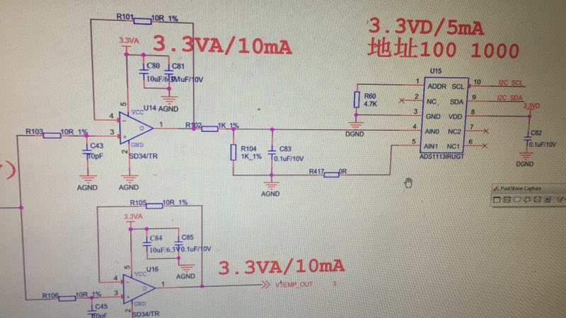
My customer is using the ADS1113 now, the schematic is below. When the AINP and AINN is 0v, the output is 0v. When the AINP to AINN is 600mv, the output is 620mv. Could you please help check why? Thanks.
With 0V reporting 0V from the ADC, and the error coming with some input signal, this sounds like a gain error. For 20mV of error on a 600mV signal, this is about 3%, which is rather large. This measurement is for a 600mV DC signal, correct?
To debug this error, I would start with a few tests. Read back the registers and confirm the ADC range. Report the ADC data. Make sure that multiple readings are taken, and that there isn't some sort of settling from the op amp and input circuitry.
Measure the input voltage at the inputs (across R104 or C83) and make sure that R417 is really 0V. Use a precision multimeter for the measurement. Note that using a low quality handheld meter might give a large error especially if the 620mV is small compared to the range setting on the multimeter.
What is amplifier U14? Is it possible that it is unstable, or that the offset is large, and the customer is measuring the input voltage before the buffer.
I've worked with this ADC many times. I find it to be an accurate ADC and easy to work with. I'm sure we'll be able to debug this error.
The amp is something like TLV6001, It should have connection with the amplifer circuit, because we test the voltage of the AINP and AINN with a fluke meter. The voltage isn't accurate enough(20mv gap). Thanks.
I'd still like them to read back the configuration register to know how they have the device set up. Also, it would help to have the ADC raw data in output code, so that I can see that there isn't a problem in the conversion value.
I had thought that the TLV6001 might be unstable because the op-amp can't drive much capacitive load. However, with 1kΩ of resistance in front of the 100nF load, it looks like the decoupling of the load makes the amplifier stable enough. I ran a simulation to check
One other thought that I had was that they have separate analog and digital grounds on their board. If they have a ground loop voltage, then they may be measuring the voltage from the wrong ground, or the ground loop voltage may be causing some other measurement error. Also, the supplies cannot be isolated and the input for the ADC cannot be floating relative to the ADC ground.