This thread has been locked.

If you have a related question, please click the "Ask a related question" button in the top right corner. The newly created question will be automatically linked to this question.

ADS1220: Use AINx pin to output IDAC and sample voltage the same time

Part Number: ADS1220

Hi team,

My customer is using ADS1220 in their O2 detection project. They use it to measure two input signal, one differential pair used to measure O2 sensor input signal; Another sensor is 2-wire RTD.

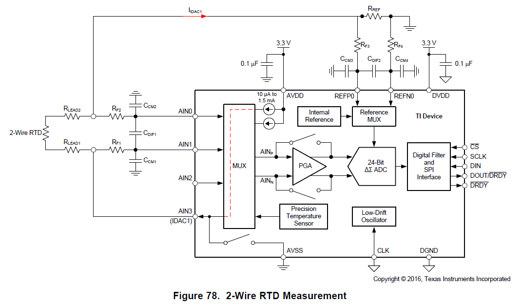
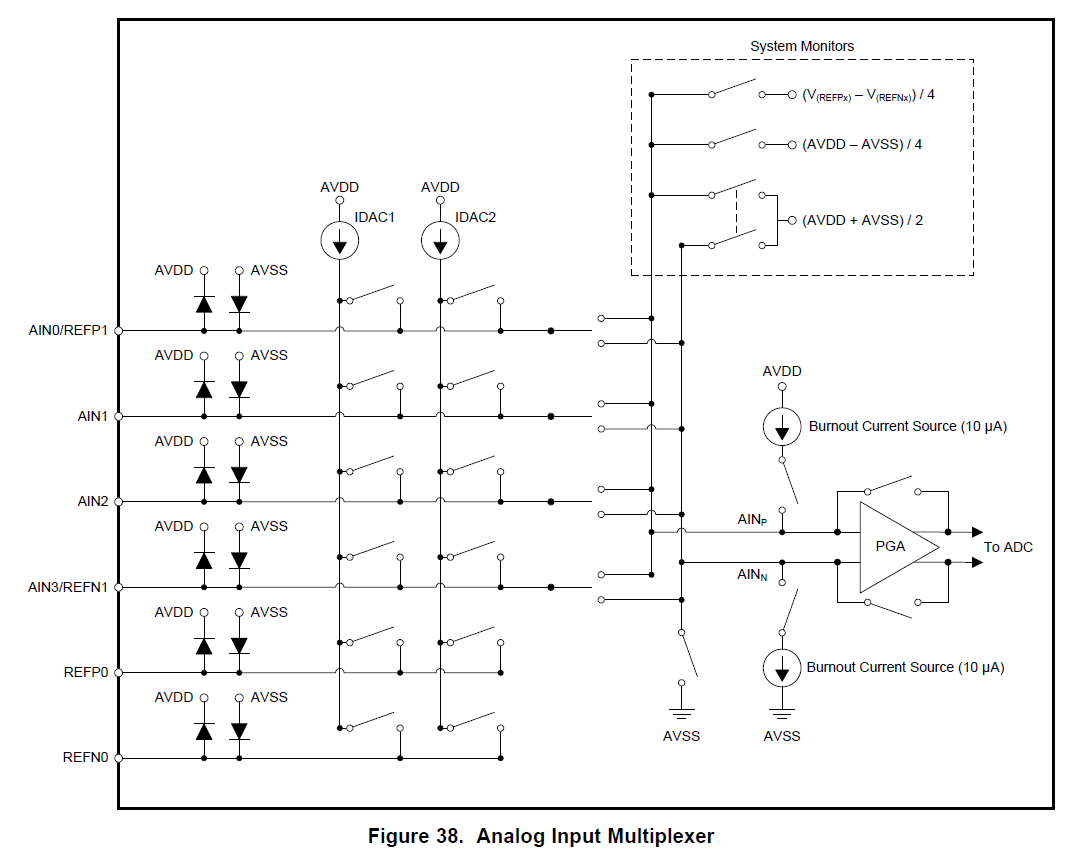
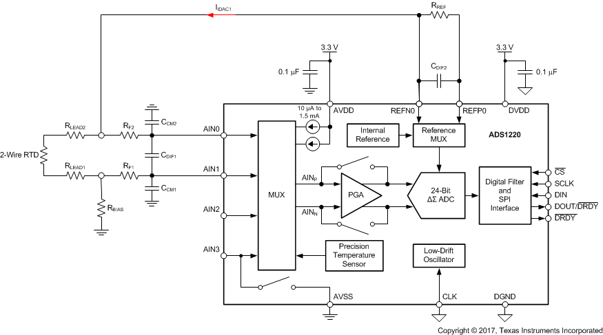
As we can see from datasheet P55 figure78, the recommended ratiometric measurement circuit need 3 AINx pins. But there is only two AINx pins left, so I wander if we can use (take the circuit on P55 as example) AIN1 to our put the IDAC, and also use AIN0, AIN1 to measure the differential input voltage of RTD. From the input structure on P20 figure38, I think AINx pins can be the IDAC output and voltage input same time, but I’m just not sure. So please give some suggestions to this problem. 

Thanks and Best Regards,

Will

  • Hi Will,

    It would be possible to route the current out AIN 1, but that will introduce additional error through any series resistance in the filtering path (and any PCB trace resistance).  I would suggest using a high-side reference.  Note there are some things turned around on the new figure compared to the old one (in particular REFP0 and REFN0).  The IDAC current is routed out REFP0 through the reference resistor and to the RTD. Another resistor is required (Rbias), which will bias the RTD into the correct common-mode input range for the ADS1220.  You would have to size the resistors appropriately for the temperature range being measured and the IDAC current that will be used.

    Best regards,

    Bob B