This thread has been locked.

If you have a related question, please click the "Ask a related question" button in the top right corner. The newly created question will be automatically linked to this question.

TLC3541

Other Parts Discussed in Thread: TLC3541, OMAP3530

Hello everybody!

I have a problem which I can solve with my software. However, I would like to know the reason this happens.

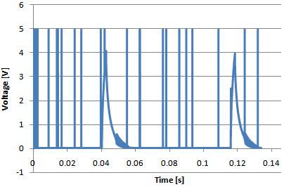
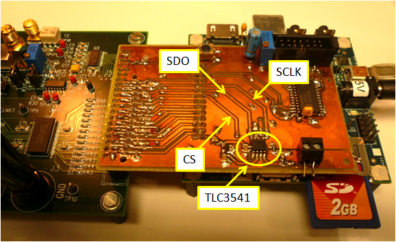
I have been using a TLC3541 and my signal is just an exponential decay, the period of my signal is 77ms (13Hz) and the clock for my ADC through the SPI interface gives me a 133KSPS which is less than the maximum 200KSPS for the ADC.

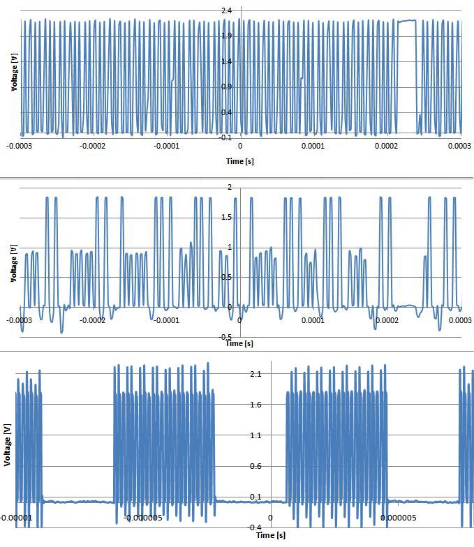
When I plot the digitalized signal, it looks exactly how it should be, except that there are some random points reaching the ADC full scale (5V). What is happening there?

Thanks a lot!

The following graph shows this problem:

  • Hi Frederico,

    Are you able to send a screen shot of your SPI timing?  I am wondering if perhaps you are short cycling the TLC3541 which causes the device to output 0x3FC0.

  • Hello Tom,

    Thanks for your fast answer. I am not sure if the graphs will help you. I was only able to get some data output synchronized with the SCLK from my the SPI Master which is the McSPI4 from a Beagle board. The chip select (CS) is kept low during the whole data transfer and goes to high when the transfer is done.

    The last graph is the SCLK. I zommed in, the horizontal resolution gets a lot better and it is possible to see clearly the clock. This graph was saved separately from the two first.

    Thanks!

  • Hi Frederico,

    What are you using to capture that waveform?  The high level of the SCLK in the last frame looks like it is barely meeting the Vin_hi specification of the datasheet and it looks like there is a lot of ringing on the clock.  Do you have access to a four channel scope where you can capture the SCLK and SDO triggered off the /CS input?

  • Hello Tom,

    I have been using a 2 channel oscilloscope and I have to stop the data acquisition and save the data from channel 1 and 2 as csv data. I am not sure if I could get a 4 channel oscilloscope.

    The problem is that I use McSPI4 as master SPI through the expansion header of BeagleBoard and that is directly connected to my TLC3541. The SCLK signal which comes from this board probably can not be changed and I believe that amplifying this signal is probably not the best idea neither. Since the OMAP3530 and the TLC3541 are both from Texas Instruments, I could not imagine that the problem would be with the SCLK voltage amplitude.

    I could not find the Vin_lo in the datasheet. Do you mean: High level control input voltage, VIH = 2.1V and Low level control input voltage, VIL = 0.8V ? 

    Thanks!

  • Sorry for the delay Fredirico,

    Yes - I meant VIH, sorry 'bout that.  I'm not suggesting that you need to amplify the signal in any way, I'm just trying to understand why it looks like there are 16 transitions at what looks like 2.1-2.2V and another 8 mixed in there around 1.7V or so.  Can you take a picture of the setup?  How long are the wires you are using between the Beagle Board and the TLC3541?

  • Hello Tom,

    I know what you mean, I have noticed these 1.7V peaks. However, I don't think that could be the problem once the output goes to 0x3FC0 only about 7 or 8 times for each 2000 points plotted on the graph.

    The SCLK, SDO, CS have a length of something in between 3 - 5 cm  (1.2 - 2 in). You can see that in the attached picture.  

    Thanks for trying to help!

    Frederico