This thread has been locked.

If you have a related question, please click the "Ask a related question" button in the top right corner. The newly created question will be automatically linked to this question.

ADS8691: Problem configuring ADS8691

Part Number: ADS8691

Hi

I'm having trouble configuring the ADS8691 for 0-5.12V input range. I can correctly readout the ADC value, but it stays in -12V - +12V range, whatever I do.

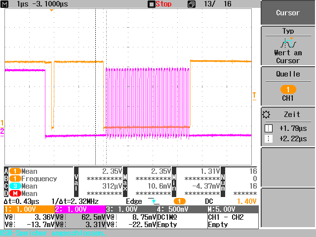
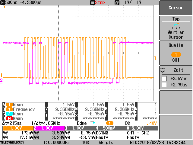
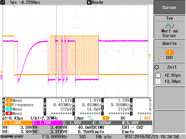
Here are some scope shots of the configuring (sorry, I could not attach all 4 probes because the testpoints were forgotten) :

yellow: CS/Convst, magenta: SCLK

yellow: SCLK, magenta: SDI

yellow: SCLK, magenta: SDO

Can you help me on what I'm doing wrong?

Kind regards

Claudio

  • Hello Claudio,

    Try programing the registers, then read the registers you programmed, this will help to see if and where the issue is.  Table 3 of the datasheet will help with the range selection, also page 41 helps explain how to write to registers. Are you programming any other registers, do those work correctly?

    I would also suggest using a known DC input voltage to check the ADCs results

    -Cynthia

  • Hi Cynthia

    Funny enough this solves the problem. Writing alone did not work. But now when I read it after writing it works.
    Thanks for the hint.

    Claudio
  • Hello,I'm very happy for you.I have been trying to communicate with ADS8691,but failled to read the register.Can you show me the demo code.Thanks firstly.The following is the codes.

    // Transmit data
    GpioDataRegs.GPBDAT.bit.GPIO57 = 0;
    ////////////////write register//////////
    spi_xmit(0xD014);
    // Wait until data is received
    //while(SpiaRegs.SPIFFRX.bit.RXFFST !=1) { }
    // Check against sent data
    //rdata = SpiaRegs.SPIRXBUF;
    delay_loop();
    spi_xmit(0x000B);
    GpioDataRegs.GPBDAT.bit.GPIO57 = 1;
    // Wait until data is received
    //////////////read register///////////
    GpioDataRegs.GPBDAT.bit.GPIO57 = 0;
    spi_xmit(0x4814);
    delay_loop();
    spi_xmit(0x0000);
    //while(SpiaRegs.SPIFFRX.bit.RXFFST !=4) { }
    delay_loop();
    result = SpiaRegs.SPIRXBUF;
    // if(rdata != sdata) error();
    GpioDataRegs.GPBDAT.bit.GPIO57 = 1;
    //delay_loop();

  • hello,I have the problem.Firstly,I can read the data in default condition .Then I tried to write the gegister,but failed.The following is the code.Can you give me some advises?
    ////////////////write register//////////
    GpioDataRegs.GPBDAT.bit.GPIO57 = 0; //pull down CS
    spi_xmit(0xD014); //write register
    delay_loop();
    spi_xmit(0x000B); //set range 1.25*verf
    delay_loop();
    GpioDataRegs.GPBDAT.bit.GPIO57 = 1; //pull up CS
    //////////////read register///////////
    GpioDataRegs.GPBDAT.bit.GPIO57 = 0;
    spi_xmit(0xC810);
    delay_loop();
    spi_xmit(0x0000);
    rdata = SpiaRegs.SPIRXBUF;
    GpioDataRegs.GPBDAT.bit.GPIO57 = 1;
    delay_loop();
  • Hello Jun Sun,
    Unfortnetly TI does not have sample code. If you are having issues, please create a post and we will try to address the problem
    Regards
    Cynthia