This thread has been locked.

If you have a related question, please click the "Ask a related question" button in the top right corner. The newly created question will be automatically linked to this question.

ADS1298RECGFE-PDK: ADS1298R REV B

Part Number: ADS1298RECGFE-PDK
Other Parts Discussed in Thread: ADS1298R, ADS1298

we are using ADS1298R for our application.we are able to write/read register in ads1298 and also able to read data using ADS1298R.

But as we are not trying to change options of output data rate & gain etc. using USB protocol. we are not able to update it every time.

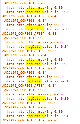
i have done debugging we are getting USB command correct every time according to we are able to read data of register correctly every time. then we are masking the bits and then updating regData variable according to command it is also updating every time correctly then we try to write register and read it again but it not working properly.

I have attached screenshot below.

so if someone can suggest me the solution that would be very helpful.

  • Hi Saloni,

    Thanks for your post.

    If you are able to read/write registers in the initialization part of your program, then the process is the same if you wish to update them afterward. First you need to send "SDATAC" in order for any other SPI commands can be recognized. Are you doing this in your code?

    Can you send us an example of the bytes you send when you try writing to the CONFIG1 register?

    Regards,
  • we are sending it in initialization (only once.) we need to send it every time??(for writing every register?) 

     we are sending SDATAC  also when we acquire the data and then we want to change register for next Data Acquisition.
    so if we are only in read/write mode then why  we should send SDATAC every time?
  • Write Function:

    1. CS Low
    2.Transmit wreg commnad
    3.Delay
    4.send the no of register want to write-1
    5.Transmit the Value
    6.CS High

    before writing we are reading previous value then masking the bits and then writing the value as per command.

    regData = g_ads1298_config1 &~ ADS1298_DR_MASK;
    regData = regData | Drset; //Drset hex value as per command

    then writing redData in CONFIG1.
  • Hi Saloni,

    No, you only need to initialize the register settings one time.

    Any time the device is in RDATAC mode (which is default at power-up) and you need to change a register, you must first send SDATAC.

    When you finish changing your registers, then you can send RDATAC again and monitor for /DRDY interrupts for continuous data collection.


    Regards,

  • Ryan 

    we have develop our application such that we can write any register value any time as per settings required but what happens is, it does not writes register every time.

    Note: Here I mean changing register values very often manually,I am not in RDATAC mode.

    case1 : If i am manipulating gain settings then it works up to certain attempts but after some time it starts misbehaving and does not write correct value.

    case2 : If i am changing sample rate register then it works for some attempts then again it does not writes correctly.

  • Hi Saloni,

    Ok, I understand you are using RDATA mode.

    In that case, it may be possible that you are violating the required command decode time for multi-byte commands (i.e. WREG and RREG). This spec, (tSDECODE) is the minimum amount of time one byte must take to send and is specified as 4 master clock periods (tCLK). If your SCLK frequency is relatively fast and one byte takes less than 4*tCLKs to send, you must insert a delay before sending the next byte in the command. This is explained on page 60, Figure 68.

    Can you share what your master clock frequency and SCLK frequency are?

    Best Regards,
  • we are running  spi at 3.4 MHZ, FCPU is 216 MHZ so delay needed is 1.98 us. so we have added 2us delay in read/write function.

    any other additional delay is needed?

  • Hi Saloni,

    I don't know what you mean by "FCPU." The master clock frequency I'm referring to is the clock signal provided to the ADS1298R CLK pin. It cannot be 216 MHz.

    If your delay is 1.98 us, then I assume you are using a 2.02 MHz CLK input? That's ok, but can you not use the internal 2.048 MHz clock instead?

    Since you are using SCLK = 3.4 MHz, 8 bits will be transmitted in 2.353 us, which is longer than 4*tCLK = 1.98 us. Therefore, you do not need to introduce an additional delay between consecutive bytes.

    Best Regards,