- Ask a related questionWhat is a related question?A related question is a question created from another question. When the related question is created, it will be automatically linked to the original question.
Hello,
I am using ADC14x250EVM and TSW14J56EVM combination to capture the read and capture the signals as shown in figure 2 of SLAU625. The goal of my project is to transmit the output of ADC (SO+/- pins) and SYNCb signals through fiber optic connection. I have successfully sent the serialized output signal through the fiber without any problem, however, I am having a lot of problem doing so with SYNCb. Hence, I have some questions regarding the SYNC signal:
1. The SYNC signal is sent from the receiving side, which would be the TSW14J56 in this case. Could you please explain the physical aspect of how SYNC signal works - I know when connected the sync signal asserts and deasserts with a pulse of about 14ms width, figure 1(I connect my probes and push capture button in HSDC pro to obtain the SYNC signals). I expected this to be the communicated from the TSW14J56 board to the ADC, however, when I severed the connection, I could only see a pulse of about 3.5us width come out of the FPGA board, figure 2.
What does this mean? What is the sequence of creating the assertion and de-assertion? Which chip creates assertion and de-assertion - Is it that the ADC receives the 3.5us wide pulse from FPGA and then asserts and deasserts the SYNC signal or is it that FPGA asserts the signal through that pulse and then ADC deasserts it after 14ms?
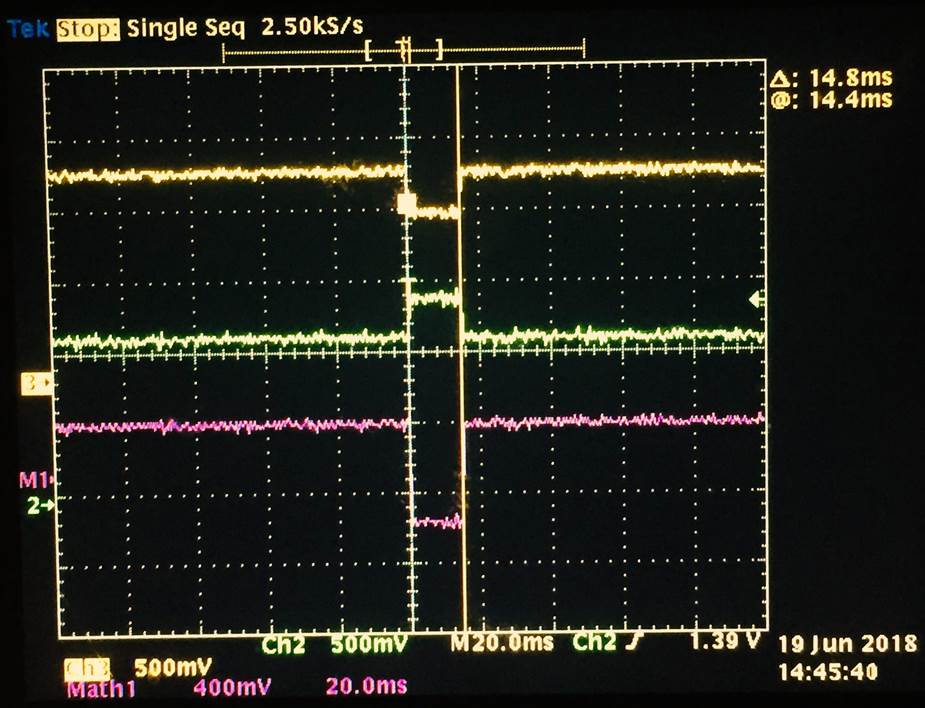
Figure 1. Original SYNC signal
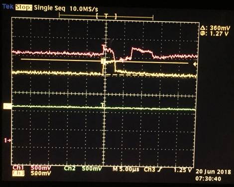
Figure 2. SYNC signal
2. The ADC configuration GUI allows control of SYNC over SPI. I can capture the signals successfully from HSDC pro if I switch to control of SYNC over SPI and hit the deassert button in ADC configuration quickly after hitting Capture button in HSDC pro. However, this is not practical. I was wondering if I could make the capture button in HSDC pro deassert the SYNC in ADC configuration GUI automatically? In other words link the two software and deassert SYNC when capture button is pushed but with certain delay. Has anybody in TI done such integrations in past?
I thank you for your help in advance.
Lizon