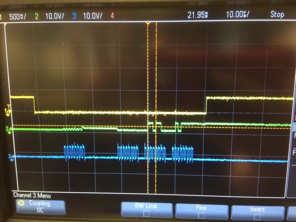
Hi,
I have been working on ADS1256 for almost a month now. I am using AVR atmega1284P 8-bit micro-controller. The issue that I am facing is that when I program the ADS, it works for less than 5 seconds and does not work again unless I remove the power and plug it back again. It works for few seconds and then the output disappears again. Please look at my code below, any help is really appreciated. The fCLKIN is 8MHz and SCK is 2MHz. The interrupt function works fine I verified myself. Everything is in the default state and I am reading conversion result at default state. Also, please let me know if my t6 calculations are right. Another thing I want to mention is, I have gaps in SPI clock after every 8 clock cycles. Does this effect the output?
Thanks.
/*
 * ADS1256.cpp
 *
 * Created: 6/13/2018 3:47:12 PM
 * Author : Ajay
 */

#include <avr/io.h>
#include <avr/interrupt.h>

#define MYUBRR 51
#define F_CPU 8000000UL
#include <util/delay.h>

unsigned char spi_tranceiver (unsigned char data);
void USART0_Init(void);
void transmit (unsigned char DATA);

int a = 0;
unsigned long adc_val = 0;

ISR(INT0_vect)
{
if (a == 0)
{
	spi_tranceiver(0x03);
	_delay_us(25);
	a = 1;
}
adc_val = spi_tranceiver(0);
adc_val <<= 8;
adc_val = spi_tranceiver(0);
adc_val <<= 8;
adc_val = spi_tranceiver(0);
}

int main(void)
{
	DDRB |= 0b10110000; //Setting the MOSI, SS & SCK as outputs and MISO as input

	SPCR |= (1<<SPE)|(0<<DORD)|(1<<MSTR)|(0<<CPOL)|(1<<CPHA)|(1<<SPR0)|(0<<SPR1); //Enabling SPI and setting freq to 2 MH. Also, setting MSB transferred first
	SPSR |= (1<<SPI2X);

	EIMSK |= (1<<INT0); //Enables INT0
	EICRA |= (1<<ISC01)|(0<<ISC00); //Interrupt INT0 on falling edge

	sei(); //Enable the interrupts

    while (1)
    {
		USART0_Init();

		transmit((adc_val >>16));
		transmit((adc_val >>8));
		transmit((adc_val));
	}
}

unsigned char spi_tranceiver (unsigned char data)
{
	SPDR = data;
	while(!(SPSR & (1<<SPIF)));
	return(SPDR);
}

void USART0_Init(void)
{
	UBRR0H = (unsigned char)(MYUBRR>>8);
	UBRR0L = (unsigned char)(MYUBRR);
	UCSR0B = (1<<RXEN0)|(1<<TXEN0);
	UCSR0C = (0<<USBS0)|(1<<UCSZ00)|(1<<UCSZ01)|(0<<UCSZ02)|(0<<UMSEL00);
}

void transmit (unsigned char DATA)
{
	while ( !(UCSR0A & (1<<UDRE0)) );
	UDR0 = DATA;
}
* ADS1256.cpp
*
* Created: 6/13/2018 3:47:12 PM
* Author : Ajay
*/
#include <avr/interrupt.h>
#define F_CPU 8000000UL
#include <util/delay.h>
void USART0_Init(void);
void transmit (unsigned char DATA);
unsigned long adc_val = 0;
{
if (a == 0)
{
spi_tranceiver(0x03);
_delay_us(25);
a = 1;
}
adc_val = spi_tranceiver(0);
adc_val <<= 8;
adc_val = spi_tranceiver(0);
adc_val <<= 8;
adc_val = spi_tranceiver(0);
}
{
DDRB |= 0b10110000; //Setting the MOSI, SS & SCK as outputs and MISO as input
SPCR |= (1<<SPE)|(0<<DORD)|(1<<MSTR)|(0<<CPOL)|(1<<CPHA)|(1<<SPR0)|(0<<SPR1); //Enabling SPI and setting freq to 2 MH. Also, setting MSB transferred first
SPSR |= (1<<SPI2X);
EIMSK |= (1<<INT0); //Enables INT0
EICRA |= (1<<ISC01)|(0<<ISC00); //Interrupt INT0 on falling edge
sei(); //Enable the interrupts
while (1)
{
USART0_Init();
transmit((adc_val >>8));
transmit((adc_val));
}
}
{
SPDR = data;
while(!(SPSR & (1<<SPIF)));
return(SPDR);
}
{
UBRR0H = (unsigned char)(MYUBRR>>8);
UBRR0L = (unsigned char)(MYUBRR);
UCSR0B = (1<<RXEN0)|(1<<TXEN0);
UCSR0C = (0<<USBS0)|(1<<UCSZ00)|(1<<UCSZ01)|(0<<UCSZ02)|(0<<UMSEL00);
}
{
while ( !(UCSR0A & (1<<UDRE0)) );
UDR0 = DATA;
}


