This thread has been locked.

If you have a related question, please click the "Ask a related question" button in the top right corner. The newly created question will be automatically linked to this question.

ADS1015-Q1: How about the DNL and PSRR of ADS1015-Q1?

Part Number: ADS1015-Q1
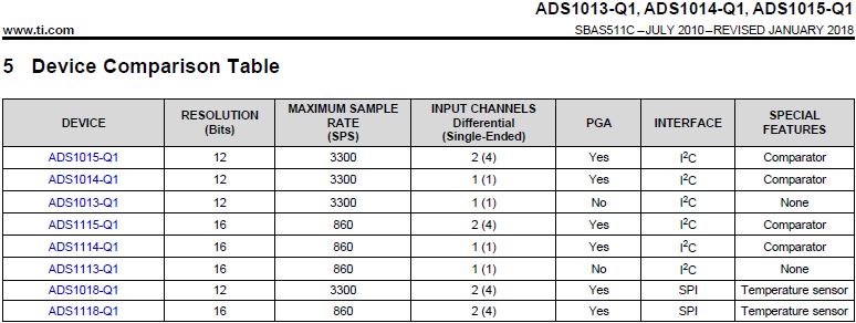
Other Parts Discussed in Thread: ADS1015, , ADS1115, ADS1013-Q1, ADS1118

Hello Team,

I don't find the DNL(Differential Nonlinearity) and PSRR(Power Supply Rejection Ratio) specification in the datasheet of ADS1015 .

Please provide the relevant data.

Best regards,
DY

  • DY,


    DNL and PSRR are not specified for the ADS1015-Q1. However, the 12-bit ADS1015-Q1 is based on the 16-bit ADS1115, using the same ADC construction and will have the same basic specifications.

    While the DNL is not listed for the ADS1115, the INL is less than 1 LSB for the 16-bit level. Because of this, the DNL must be significantly less than 1 LSB at the 12-bit level for the ADS1015.

    For the ADS1115 PSRR, the offset power-supply rejection is typically 1 LSB/V at the 16-bit level, This is the equivalent of 1/16 LSB/V at the 12-bit level. The ADS1115 also has a gain power-supply rejection of 80 ppm/V as a typical specification, which should be the same in the ADS1015.


    Joseph Wu
  • Hi Joseph,

    Thanks for your kind reply.

    My customer has some  additional questions as following.

    1. What's the reference voltage of ADS1015-Q1 when using VDD=3.3V?

    2. What's the tolerance of the reference voltage if the VDD range is 3.2V ~ 3.4V?

    3. Do you have any data on the total error vs input signal of ADS1015-Q1 like graph as below?


    4. As for the ADS1013-Q1, is it possible to configure two single-ended inputs?
       Because the datasheet  seem the the ADS1013-Q1 can support one differential input or one single-ended input as table below.


    Best regards,
    DY

  • DY,

    I'll answer your questions in the order they were asked in your last post.

    1. The reference voltage is not set up as a true voltage inside the ADC. It is capacitively sampled as components of the bandgap voltage (near 1V). For the different ranges, we use larger capacitors to make a larger sample. Note that for large ranges (±6.144V as an example) that are larger than the supply voltage, the input voltage should not go beyond GND and VDD. While the input will be measured correctly, the output data will not use the entire measurement range.

    2. The reference voltage tolerance is measured by the gain error. The gain error of the ADS1015-Q1 is 0.05% typical and 0.25% max. This is the same as having a reference voltage tolerance of 0.05% typical and 0.25% max.

    3. The figure from the ADS1118 comes from the sum of errors from the noise, offset and gain error. You can do the same graph by adding together a 0.25% max gain error, a 0.5 LSB offset, and approximately a 0.5 LSB noise. The noise is an approximate value. I don't have an exact value for the noise, but it is less than 1 LSB. Here's the figure I generated:

    4. It is not possible to configure the ADS1013-Q1 for two single-ended inputs. The one single-ended input is measured by attaching AINN to ground with AINP as the other measurement input.

    Joseph Wu