This thread has been locked.

If you have a related question, please click the "Ask a related question" button in the top right corner. The newly created question will be automatically linked to this question.

ADS7952 input multiplexer / photodiode / transimpendanceamplifier

Other Parts Discussed in Thread: ADS7952, OPA333

Hi,

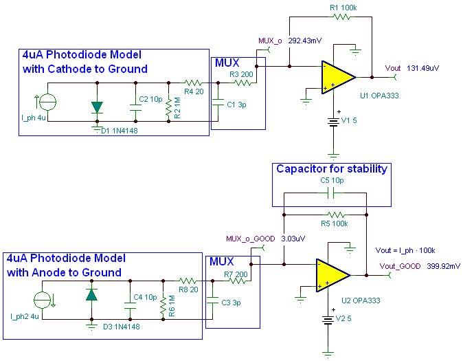
I'm here again with a new problem. I'm using a ADS7952 to measure the photocurrent of 12 photodiodes (two in one package, with a common cathode). Because i want a linear relation between light intensity and photo current i try to use a transimpedance amplifier, and because I have to save board space and power I try to use the TIA between the MXO and the AINP of the ADS7952:

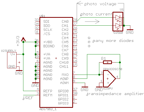
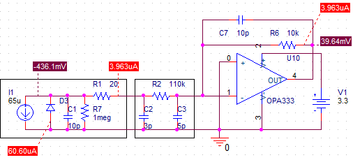
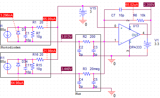
The OP amp with the feedback resistor keeps the MXO at ~0V. The problem: if a enable, CH0, there is a voltage drop of ~250mV between MXO and CH0, at a photo current of ~3.8µA. If I use the TIA without the ADS7952 (at the same lightning conditions) the photo current is ~45µA.

The 3.8µA photo current and the 250mV voltage drop equals a resistance of 65kOhms, which is much more than the 200 Ohms specified in the datasheet (p. 42, fig. 59).

Am I doing it wrong, or is ther a more fundamental problem with pulling current from multiplexer inputs?

Best regards,

Paul Roßmann


  • Hello Paul,

    I see that you have the diode cathodes connected to ground in order to have the photocurrent direction from amplifier to ground. However, this current direction is incorrect because the diode photocurrent actually goes from cathode to anode. This is causing the OPA333 to aim for a negative voltage, which is impossible to get with its single supply. Consequently, the OPA333 output is driving the voltage MXO and forward biasing the photodiode.

    In general, photodiodes should not be forward biased because they could get damaged from driving to much current. In the S6560’s datasheet, it is explained that the photodiodes typical performance is obtained if this is biased with 10V reversed voltage or -10V.

    My recommendation is to simply reverse the orientation of the diodes in the schematic, put new diodes, and use at least a 10kohm feedback resistor for R1.

    Regards,

  • Hello again Paul,

    These simulations can approximately replicate your issue and I hope they can clarify my previous recommendation.

    I noticed some stability issues after doing a transient analysis, , so I also recommend adding a 10pF capacitor in parallel with the 100k resistor.


    There will be stability issues without a capacitor in parallel with the feedback resistor.


    With a 10pF capacitor

  • Hello Rafael,

    Thanks for your effort with the simulations; I'm going to put the capacitor in there to avoid those stability problems.

    And as you mentioned absolutely right, the direction of the photodiodes is wrong. But this was caused by me getting the pinout wrong (I thought I had the photodiodes as shown in the schematic, but they were actually with the common cathode connected to the ADS7952).
    The problem which remains is still the same: I measure the current from the CH0 pin to the photodiode and the voltage of MXO and CH0 with reference to ground.

    MXO / GND: 0.2mV
    CH0 / GND: -375mV
    current:   3.8µA

    So the situation looks much more like this (not exactly, I think because of the different diode characteristics):

    The 65uA for I1 are determined with the photodiode short circuit through an ampere meter. The 110kOhms inside the multiplexer are choosen to fit the measurements. The open circuit voltage of the photodiode at the given lightning conditions is 402mV.

    Again, the datasheet gives an equivalent circuit for the multiplexer which is essentially a resistor of 200 Ohm, so I expected to see virtually no voltage drop between MXO and CH0. Are there any clamping diodes to the ground or power supply rails on the multiplexer input, or is the resistance of the multiplexer degrading at voltages very close to the power supply? Or simply don't I undestand it?

    Best regards,

    Paul Roßmann 

  • Hello everyone,

    i've got a question concerning the specification of the multiplexer: is the "absolute input range" in the data sheet on page 5 meant to be the range for the AINP pin or for the CHn pins?

    The Problem is that if i turn of a channel, the voltage at the affected CH pin drops below -0.3V, which is lower than allowed by the absolute maximum ratings. That may be a cause of my problems. One viable workaround for this could be to raise the ground level for the anodes of the photodiodes an the negative input of the op amp by ~0.4V to avoid this situation.

    It would be nice if i could get a confirmation for my assumptions.

    Best regards,

    Paul Roßmann

  • My final solution:

    inverting the TIA circuit by applying 3.0V to the positive input of the op amp, connectiong the cathodes to 3.0V and the anodes to the multiplexer.

    Best regards,

    Paul Roßmann