This thread has been locked.

If you have a related question, please click the "Ask a related question" button in the top right corner. The newly created question will be automatically linked to this question.

ADS1293: ADS1293 3-Lead ECG noise

Other Parts Discussed in Thread: ADS1293, ADS1293EVM

art Number: ADS1293

Hi Sir

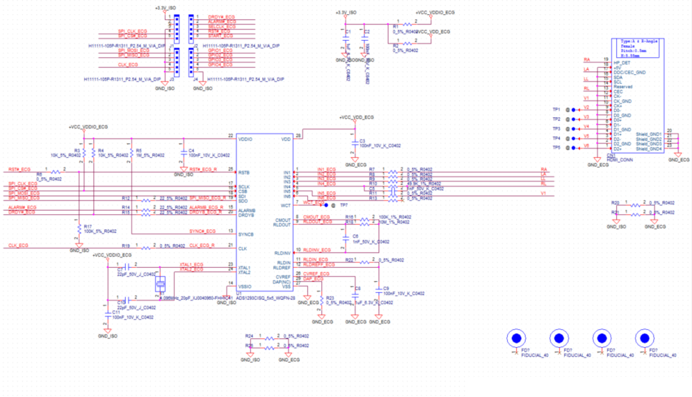
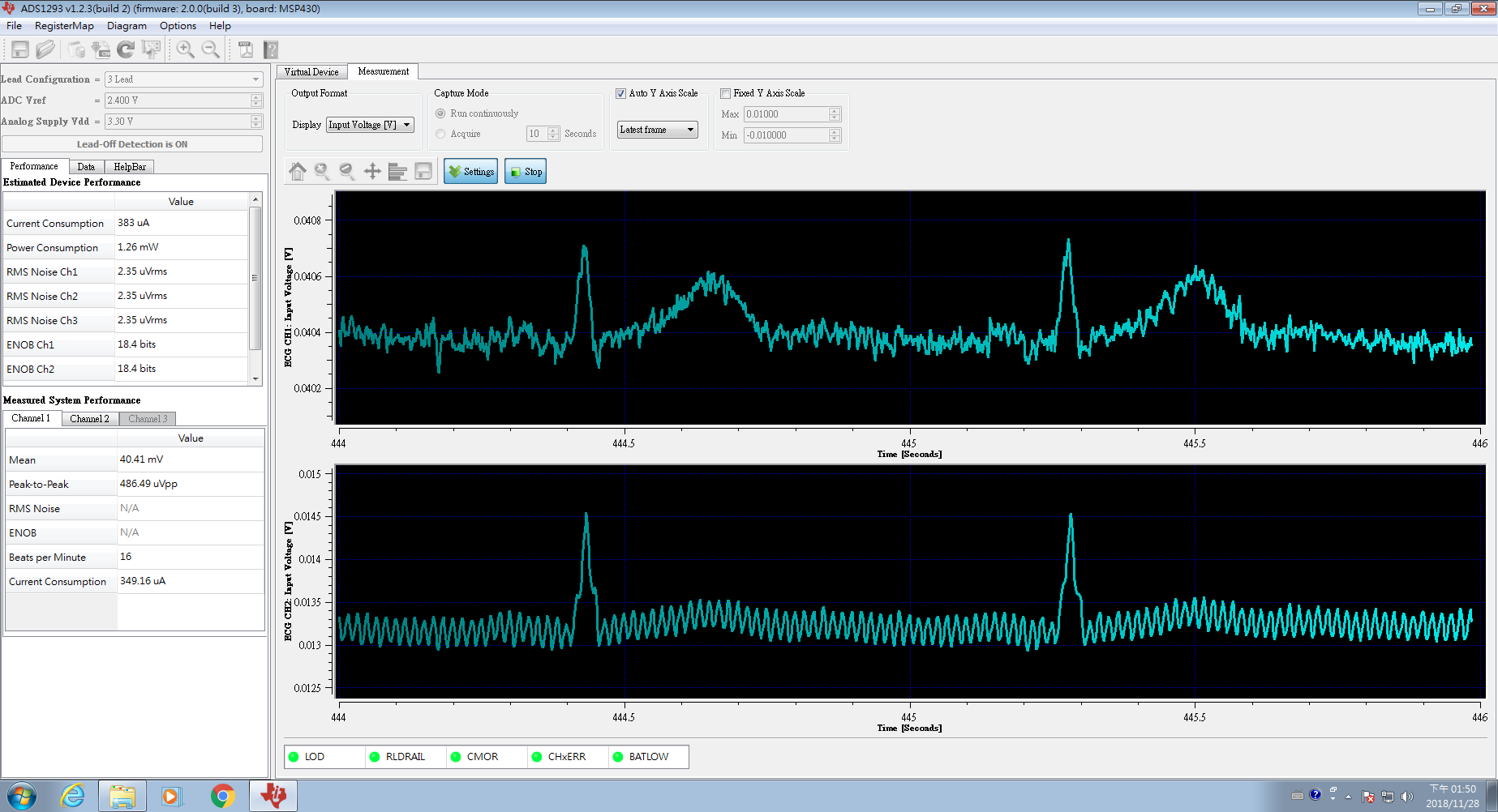
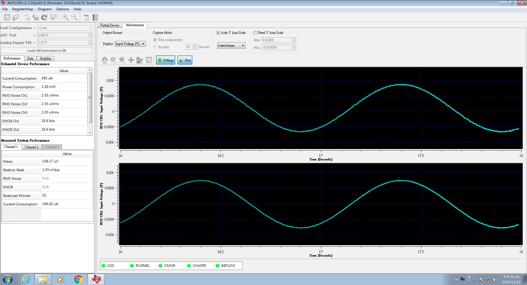
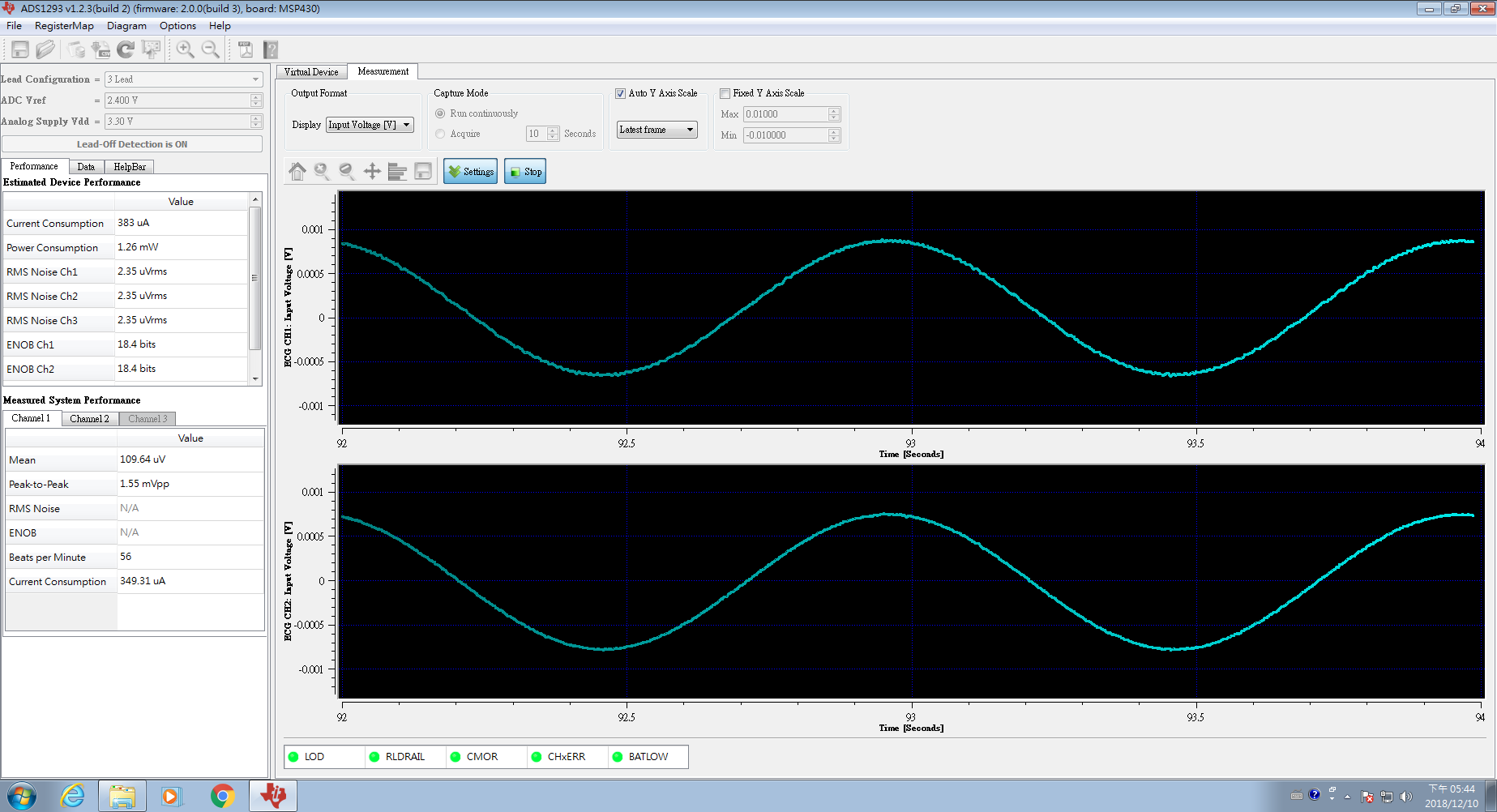
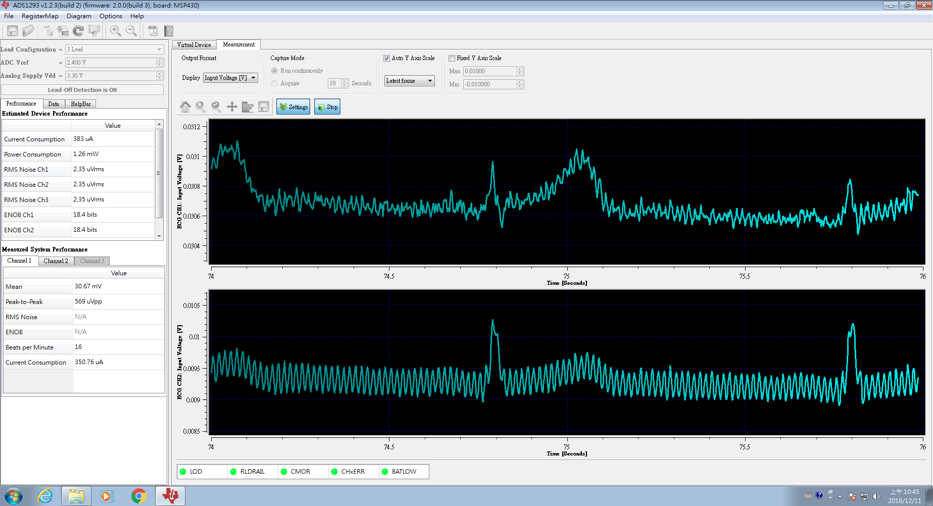
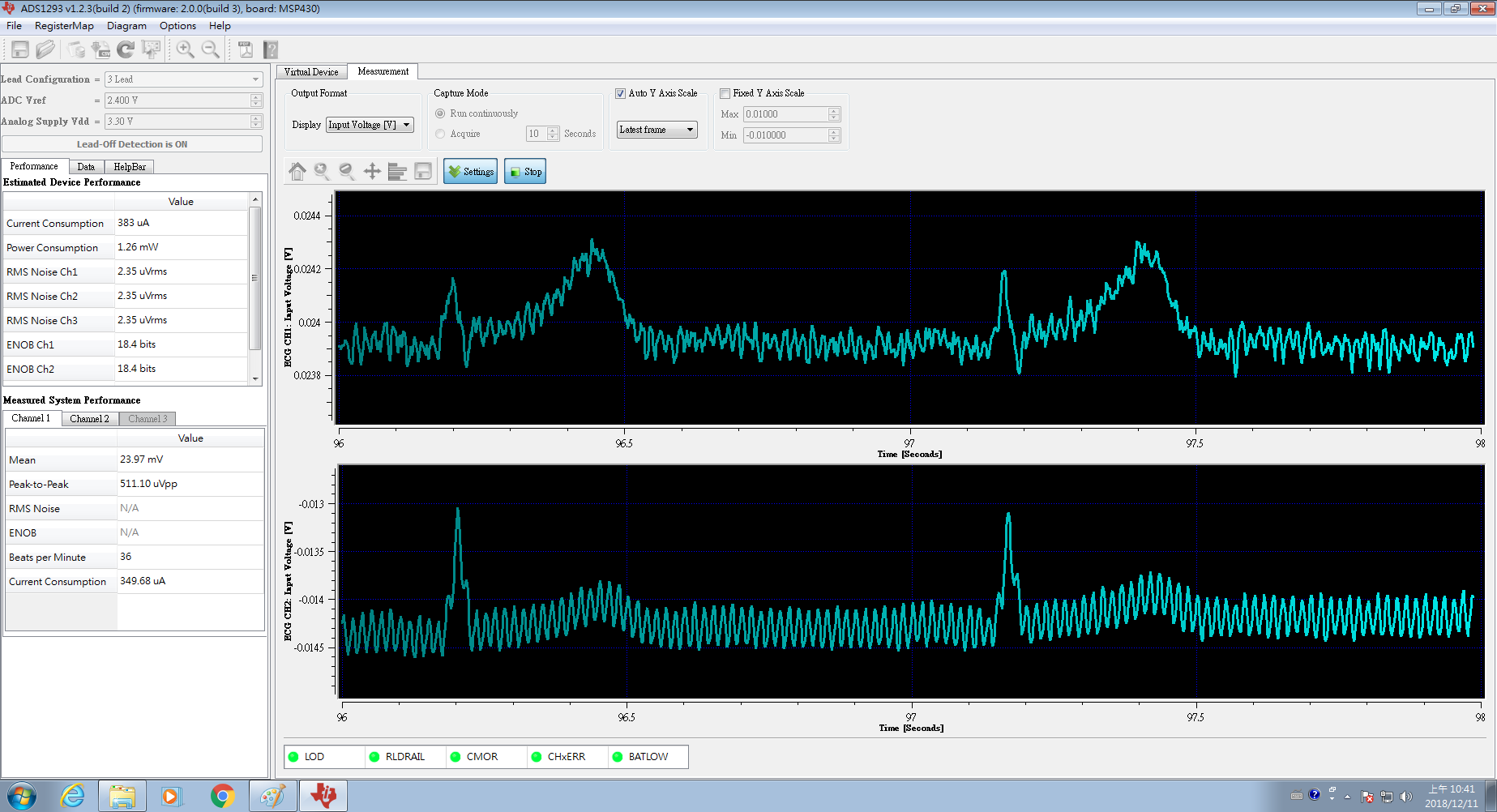
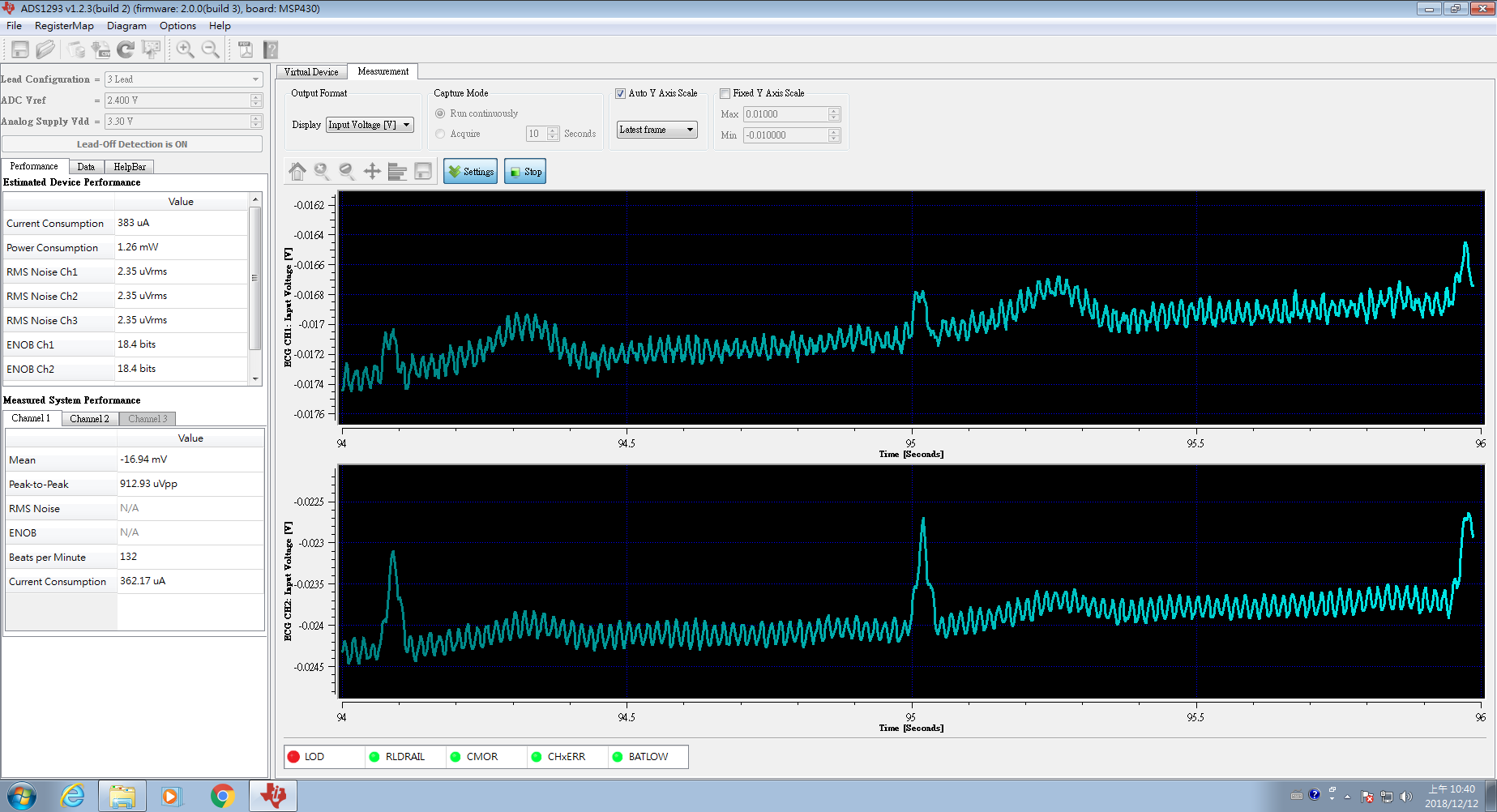
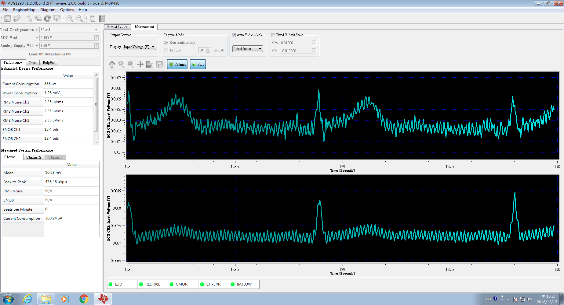
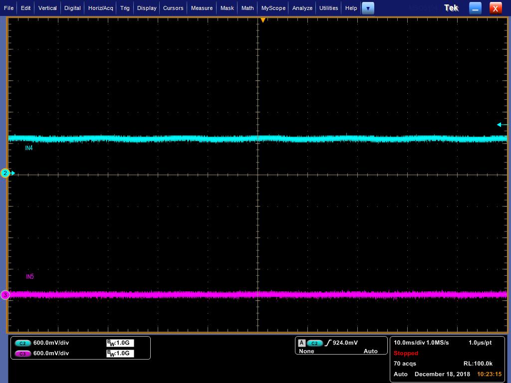
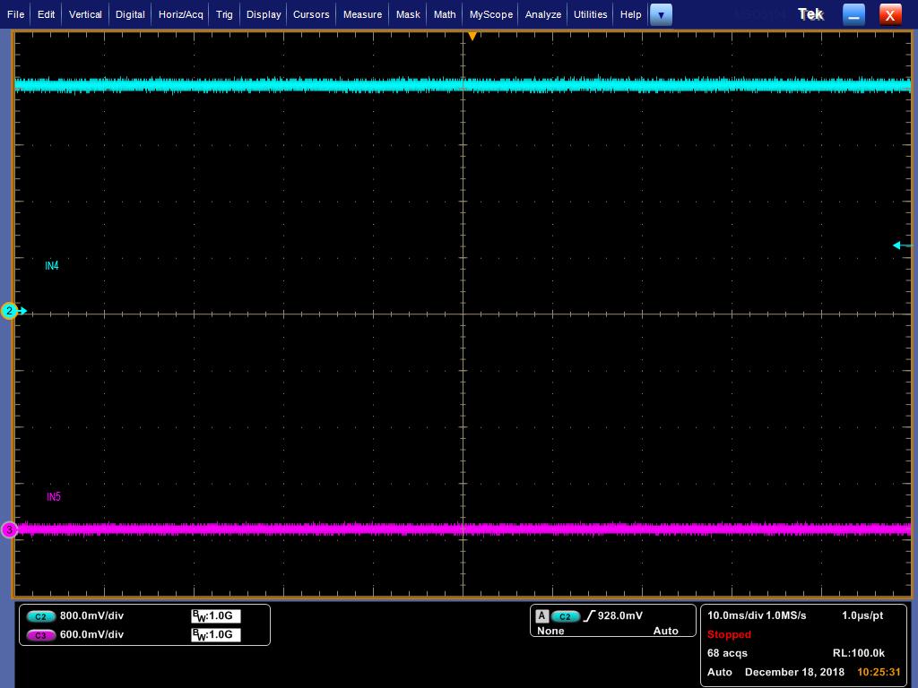
Please refer below picture. (schematics & waveform)

According application note SBAA188 (Improving Common-Mode Rejection Using the Right-Leg Drive Amplifier)  figure 7  to add RP (50K) & CP.

According TI Precision Lab discussing OP AMP bandwidth part 1 page 10 calculate CP value = 1nf.

The waveform use ADS1293EVM to measure. Do you have any suggest to further reduce noise?

  • Hello Shih,

    Thanks for your post and welcome to the forum!

    I don't see a net for the RLD electrode connection. Is the patient being properly biased?
  • Hi Alex,.
    I think that SHIH mean RLD amp configuration internal, or you could suggest RLD circuit to him ,.
    thanks

    regards,
    Philip
  • Hi Shih,

    Can you post your register settings so we can make sure that the RLD circuit is properly configured for the IN4 pin?

    It looks like either R15 or R16 ( I cannot tell from the picture) connected to CMOUT is 100k instead of 10k. You can refer to Figure 7 of the ADS1293EVM User's Guide for reference.
  • Hi Alexander

    register setting as below

    address--value
    0x00 -----0x00
    0x01 -----0x11
    0x02 -----0x19
    0x03 -----0x00
    0x04 -----0x00
    0x05 -----0x00
    0x06 -----0x00
    0x07 -----0x0f
    0x08 -----0x01
    0x09 -----0x00
    0x0a -----0x07
    0x0b -----0x00
    0x0c -----0x04
    0x0d -----0x00
    0x0e -----0x00
    0x0f  -----0x00
    0x10 -----0x00
    0x11 -----0x00
    0x12 -----0x04
    0x13 -----0x00
    0x14 -----0x00
    0x15 -----0x00
    0x16 -----0x00
    0x17 -----0x05
    0x18 -----0x00
    0x19 -----0x00
    0x1a -----0x00
    0x1b -----0x00
    0x1c -----0x00
    0x1d -----0x00
    0x21 -----0x02
    0x22 -----0x02
    0x23 -----0x02
    0x24 -----0x02
    0x25 -----0x00
    0x26 -----0x00
    0x27 -----0x08
    0x28 -----0x00
    0x29 -----0x00
    0x2a -----0x00
    0x2b -----0x00
    0x2c -----0x00
    0x2d -----0x00
    0x2e -----0x33
    0x2f  -----0x30
    0x30 -----0x00
    0x31 -----0x00
    0x32 -----0x00
    0x33 -----0x00
    0x34 -----0x00
    0x35 -----0x00
    0x36 -----0x00
    0x37 -----0x00
    0x38 -----0x00
    0x39 -----0x00
    0x3a -----0x00
    0x3b -----0x00
    0x3c -----0x00
    0x3d -----0x00
    0x3e -----0x00
    0x3f  -----0x00
    0x40 -----0xff
    0x50 -----0x00
    0x60 -----0x00
    0x62 -----0x00

  • Hi Alexander
    The waveform which I used ADS1293EVM board to measured. The EVM board CMOUT to RLDINV resistor value is 10K when I measured. The schematics resistor is my drawing mistake. I will change it to 10K, thanks for your check and remind.
  • Hi Alex,
    We are using In4 as RLD drive and use 50K ohm for Rp ad 1nF for Cp. May i have your comment on anything we can do to improve the waveform? thanks!

    PY Tsai
  • Hi Shih,

    I apologize for the delay in response and thank you for providing the register settings.

    The biggest issue I see is that your inputs do not have filtering. I recommend adding a RC filter to your electrode inputs.

    I would also recommend disabling lead off detection for troubleshooting.

    What are you using to generate the input signal? A patient simulator? Is the noise still present on the output if you input a clean sine wave?
  • Hi Alexander

    As below waveform is using patient simulator & output sine wave for you refer.

    1. lead-off (disable)

    2.lead-off (8nA)


    About your recommend RC filter for electrode inputs . May I refer electrode input RC filter of ADS1298EVM? or do you have other recommend RC filter circuit?

    As below waveform is using ADS1298EVM RC filter to measure human body. not use patient simulator.

    1.lead-off (disable)

    2.lead-off (8nA)

    Do you have any suggest to work on to further reduce the noise?

  • Hello Shih,

    Using the RC filter from the ADS1298EVM is fine.
    This is certainly 60Hz noise that should be canceled out, however something that I didn't notice from your registers in my last post is that the ID register 0x40h is not reading back correctly. I also noticed that in register 0x17h, the analog pace output is connected to RLDIN, try disabling this.

    Can you verify that the common mode voltage is present on the IN4 pin?
    If you change the register so that RLD is output to IN5, do you see the common mode voltage on IN5?

    I found a couple of posts that may help:
    e2e.ti.com/.../2026199
    e2e.ti.com/.../1046151
  • Hi Alexander

    We find ID register error is tool should be click read icon at register 0x40, if we click read icon the ID register is 0x01.

    as below waveform are disable pace output (register 0x17h setting 0x01)

    but we find LOD sometimes will show error. Is it correct behavior?

    1.disable pace output(register 0x17h setting 0x01)

    2)disable pace output(register 0x17h setting 0x01) & disable Lead-off

    I have no idea how to confirm common mode voltage on IN5 when we follow your suggest change RLD output form IN4 to IN5. Do you mean RL electrode input also change to IN5? if no, could you detail describe how do we do to confirm the common mode voltage on IN5?

  • Hello Shih,

    I see, thank you for clarifying.

    What do you mean by LOD will sometimes show error?

    I mean to probe IN4 to make sure that there is a voltage present. Then switch the register to output RLD to IN5, confirm that the same voltage is present. This voltage will be driven onto the body using the RLD electrode, couples into the measurement, and is canceled by the common mode rejection when it reaches the PGA at the input stage.
  • Hi Alexander

    I apologize for the delay in response.

    LOD sometimes will show error that I means tools Indicate error message show red color on LOD. as below picture.

    I use probe connect ADS1293EVM IN4 & IN5 and use patient simulator for 3-lead ECG to measure.please see as below pictures.

    Write 0x04 to register 0x0C

    Write 0x05 to register 0x0C

    Should I change RL electrode input to IN5 when I write 0x05 to register 0x0C ?

  • Hi Shih,

    Yes, you should change the RL electrode to input IN5 when writing 0x05 to register 0x0C.

    However, what I'm more interested in is when the RL electrode is connected to IN4 it is equal to 600mV, and when you switch RLD to IN5, IN4 is equal to 2.4V while IN5 remains at 0V.

    Looking at your registers again:
    Register 0x17 is 0x05 - 00000101b

    [2] PACE2RLDIN Connect the analog pace channel output to RLDIN pin
    0: Analog pace channel output is disconnected from the RLDIN pin (default)
    ->1: Connect the analog pace channel output to the RLDIN pin.
    Note: The right-leg drive amplifier is disconnected from the RLDIN pin and connected internally to the
    RLDREF pin when this bit is 1.

    [1 ] PACE2WCT Connect the analog pace channel output to WCT pin
    ->0: Analog pace channel output is disconnected from the WCT pin (default)
    1: Connect the analog pace channel output to the WCT pin.
    Note: The Wilson reference output is disconnected from the WCT pin when this bit is 1. The Wilson
    output can be connected internally to IN6 pin with the WILSON_CN register.

    [0] SHDN_PACE Shut down analog pace channel
    0: Analog pace channel is powered up
    ->1: Analog pace channel is shut down (default)

    This presents an issue as the analog pace channel output is connected to the RLDIN pin, however the last bit in the register is 1 which means that the analog pace channel is shut down.

    Try changing register 0x17 to 0x04. Additionally, if you can provide greater detail about the intended signal path and RLD derivation it would help me understand your register settings.

  • Hello Shih,

    While looking for a solution to your issue, I may have found a problem with your setup. Channel 4 cannot be used for RLD.

    As I mentioned in my first post - there is not a proper RLDOUT electrode. Please take a look at the ADS1293EVM User's guide to see where the RLDOUT electrode should be connected to. http://www.ti.com/lit/ug/snau138b/snau138b.pdf

    e2e.ti.com/.../1357167