This thread has been locked.

If you have a related question, please click the "Ask a related question" button in the top right corner. The newly created question will be automatically linked to this question.

ADS5263: Must the signal input to 4 input pins for operating it by 18-bit resolution?

Part Number: ADS5263

Hello,

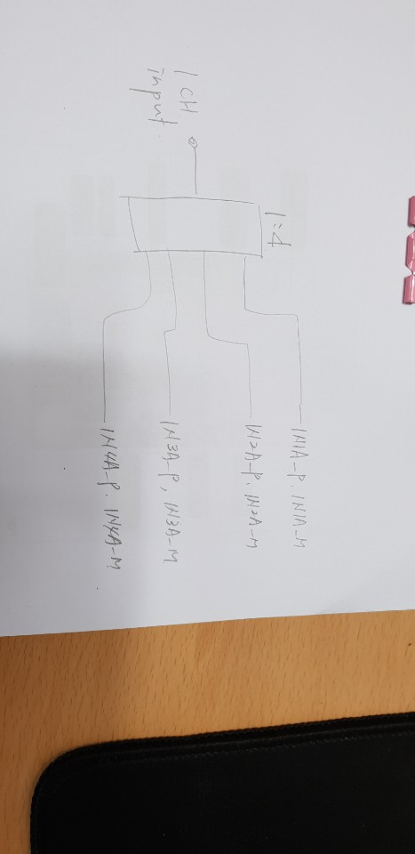
I'm going to use ADS5263 chip by ADC of receiver system. I want to have 18-bit resolution at this receiver system.

To have 18-bit resolution, must the signal be inputted to 4ea input pins?

If it is not bad, how do I do for operation of 18-bit resolution?

I want to get your help about it.

Best reguards,

  • Hi Jaden,
    How are you?
    Yes, we will look into your question on ADS5263 18-bit mode.
    I will reply to you in 2 days.

    Thank you!

    Best regards,
    Chen
  • Hi Jaden,
    How are you?
    Thanks for using ADS5263 device.
    Are you using ADS5263EVM and TSW1400EVM (used for output data capture for ADS5263)?
    (if yes, you can operate the following register settings as follows.)
    Yes, you can use one (input pins for one channel) to four channels (4 input pins for 4 channels) separately according to your application.
    To operate 18bit mode, just set the registers by the sequences as:
    Address Data
    0x00 0x0001
    0x46 0x8800
    0x0F 0x0200
    0x0F 0x0000
    0x46 0x9001
    0x25 0x0040
    Then you can capture data by using TSW1400 GUI
    and you can see the Ramp Pattern (18bit mode).

    Thank you!

    Best regards,
    Chen
  • Hi Jaden,
    How are you?
    According to the question 1,
    please look at the ADS5263 user guide's schematics (EVM design for CH IN1, CH IN2, and CH IN4 used for 16/18 bit mode):
    www.ti.com/.../ADS5263EVM

    Thank you!

    Best regards,
    Chen
  • Hi Chen,

    How are you? Thank you for your answer.

    My question is whether the signal must be applied to four input pins in order to have 18-bit resolution.
    In other words, is it impossible to have 18-bit resolution if only one signal is applied to a pin?
    So, I want to know how to setup hardware circuits to be operated by 18-bit resolution ADC.
    And, I have one more question. For 18-bit operation, can I use only the following pins?
    -. IN1A_P, IN1A_M
    -. IN2A_P, IN2A_M
    -. IN3A_P, IN3A_M
    -. IN4A_P, IN4A_M
    At this time, how do I handle the unused pins below? ; Connect to ground or dc-power.
    -. IN1B_P, IN1B_M
    -. IN2B_P, IN2B_M
    -. IN3B_P, IN3B_M
    -. IN4B_P, IN4B_M
    And, how do I handle the unused channel pins in case of using only 1 channel?
    Thank you.
    Best Regards,
    Jaden
  • Hi Jaden,
    How are you?
    We need to be clear to understand your application of using ADS5263 device.
    Here is one example, assuming you want:
    Only one analog input signal will be sent to ADS5263 device
    and only one set of digital LVDS output data (reach to 18bit resolutions) will be sent out to FPGA for capturing, right?
    If this is correct, then yes! ADS5263 can do it.
    Could you please let us know? so we can provide you more detail description.

    Thank you!

    For replying the question 1:
    For 18-bit operation, can I use only the following pins?
    -. IN1A_P, IN1A_M
    -. IN2A_P, IN2A_M
    -. IN3A_P, IN3A_M
    -. IN4A_P, IN4A_M
    Answer is: Yes!
    For question 2:
    how do I handle the unused pins below? ; Connect to ground or dc-power.
    -. IN1B_P, IN1B_M
    -. IN2B_P, IN2B_M
    -. IN3B_P, IN3B_M
    -. IN4B_P, IN4B_M
    Answer is: you can see from the ADS5263 user guide's schematic
    www.ti.com/.../ads5263evm
    which shows the above un-used pins are floating


    Thank you very much!

    Best regards,
    Chen
  •  Hi chen,

    Thank you for your sincere answer.

    I understood about your answer  as atached.

    Is this picture what you are saying for single input?

    Thank you

    Best regards,

    Jaden

  • Hi Jaden,

    How are you?

    Yes, that is right.

    If you already had ADS5263EVM and TSW1400EVM,

    then you can try the following method

    and then you can receive good results as you expected:

    Thank you for using ADS5263 device!

    Best regards,

    Chen

  • Hi Chen,

    Thank you for your answer.

    I almost understood your explanation. Here, I will ask one more question to make sure I understand.
    I understand that it can be directly connected without using an RF splitter,  when one input signal is fed
    to four input ports, IN1A, IN2A, IN3A, IN4A as follow. Is this right?
    Thank you.
    Best regards,
    Jaden
  • Hi Jaden,
    How are you?
    Thank you! Looks like this example may fit your need.
    Yes, if needed to use the RF splitter or not, it may depend on the application.
    The last picture shown if R36+INxA_P, R38+INxA_M, and C43 are directly connected
    together, they all needed to be placed as close to ADS5263's one pair input pins
    as possible (the trace distances must be <= about 4cm to ADS5263 input pins).
    Of course, please also match all the trace length and keep shortest as possible.
    I believe this is not too difficult to make it.
    Then later if you are using multiple ADS5263 devices on your system,
    in that case, you may need a splitter to share one input signal to several ADS5263 devices.

    Thank you for using ADS5263 devices!

    Best regards,
    Chen