This thread has been locked.

If you have a related question, please click the "Ask a related question" button in the top right corner. The newly created question will be automatically linked to this question.

ADS8688: EXTERNAL CV INPUTS with ADS8688

Part Number: ADS8688
Other Parts Discussed in Thread: LM5017, ADS8588H, ADS8638, OPA140, ADS8668, ISO7141CC

Hi,

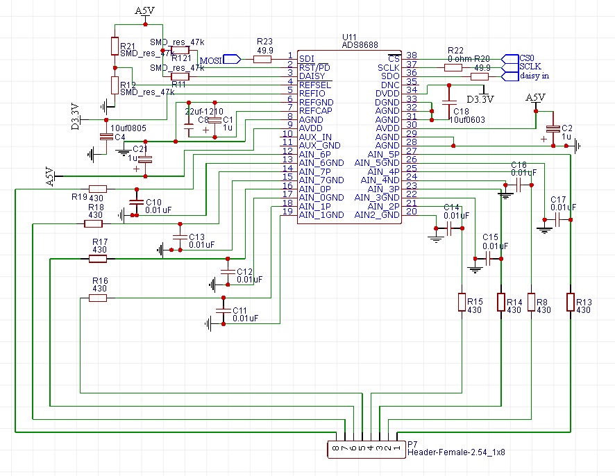
I'm trying to develop an external cv inputs reader (we are in analog modular synthesizer field) using 2 ads8688 in daisy mode . The cv inputs can be -5V to 5V or 0V-10V in range. 

In the setup we would use an external 3.3V reference because this board is meant to be used with a teensy 3.6. I attach the schematic for the first ADS8688. 

Does it look ok to you? Also, i would like to ask if you would include in the setup  (considering the use) the ISO7141 and the LM5017..

Im not an engineer, but a musician..There could be many errors, so all suggestions and corrections are highly welcomed !! thanks for your time guys!! 


  • Hello Pierluigi,

    Here are issues or suggestions for your current schematic:

    1. The DAISY pin of 1st ADC should be connected to ground(DGND). You are connecting it to A5V supply.

    2. /REFSEL is a digital input pin, and it should be connected to either D3.3V with a pull-up resistor for external voltage reference or ground directly.

    3. The external reference voltage is limited between 4.046V and 4.146V, so a 3.3V external voltage reference can not be used.

    4. Your Pin 31/32/33(AGND and DGND) are floating, all of them should be connected to ground.

    5. A balanced input RC is recommended, which means that a same value resistor is suggested between AIN_xGND and ground, please reference to 8.3.2 section and EVM board schematic under the product folder. The matching helps to cancel any additional offset error contributed by the external resistance.

    6. A solid pcb plane for ground is recommended. Also, a clean analog supply is recommended for AVDD, generally a LDO is a good solution.

    We have some isolated reference design released on TI.com, please refer to following two reference designs:

    Isolated, High-Accuracy Analog Input Module Reference Design Using 16-Bit ADC and Digital Isolator

    Isolated 16-Channel AC Analog Input Module Reference Design Using Dual Simultaneously Sampled ADCs

    Thanks.

    Regards,

    Dale

  • Hi Dale
    Thanks a lot for your fast reply and your patience, i will definitely refer to the materials you linked. To overcome the reference problem, maybe i should think about using ads8588h instead?
  • i've been studying more or less all adcs and i think that ads8638 could make the job, we have +/- 12V on the board. so it might be the best solution.

    Thanks again for your help and let me know if you agree with this

    Regards
  • Hi Pierluigi,

    ADS8588H's input range is +/-10V or +/-5V which is same as ADS8688. ADS8638 needs a front-end amplifier to drive. I'm confused about your signal, can you please let me know what the range of your signal is? Is it  -5V to 5V or 0V-10V?

    Thanks.

    Regards

    Dale

  • Hi Dale,

    Incoming signals have different ranges also because historically analog synths companies didn't really stick to a standard.

    Those are called CV (control voltage) signals. CV signals cannot have an oscillation value higher than 64 Hz (most common limit is 32 Hz)

    We have in this setup two CV signals in range of 0-10V, and all the others in the -5V-+5V range. So, both ranges at the same time 

    This would bring some sweet retro compatibility with old products.

    we would need the spi interface, and the internal reference at 2.5 V is ok  for teensy 3.6 to read, that's why i thought ads8638 could do it.

    I've put down a schematic already, but i hope it is feasible, let me know what you think about.

    OPA140 for each channel is going to make it really expensive, but if there is no other way....

    Regards

    Pier

  • Hi Pierluigi,

    The reason I asked you about your signal range is, I wanted to confirm why you want to use 3.3V external reference voltage. Based on your information above, ADS8688 is the best ADC for your design, because:

    1. ADS8688 can support both 0-10V or -5V~+5V signal, the input range can be configured by channel. It's channel-independent. Also, you only need to program the device once after power up the device.

    2. ADS8688 has a SPI interface which supports 3.3V digital logic.

    3. ADS8688's internal 4.096V voltage reference can be used directly, the internal reference has higher precision and low drift(typ 6ppm/C, max 10ppm/C) 

    4. ADS8688 has a integrated AFE(analog front-end) with ADC driver on each channel, a external amplifier is not necessary for ADS8688, but ADS8638 is a switched-capacitor input SAR ADC, so a external high bandwidth amplifier on each channel is generally required to drive the ADC.

    By the way, looks like you do not need simultaneous-sampling ADC because you are looking at all non-simultaneous-sampling ADCs, please let me know if my understanding is correct. I just want to confirm. Thanks.

    Regards,

    Dale

  • Hi Dale, 

    Simoultaneous sampling would be ok if teensy can handle it... tell me if you have something in mind

    Thing is that it makes no sense to have sampling rates superior to 44.1Ks per channel, (is already a lot i guess condered cv signals won't oscillate at more than 64 Hz) so i tought was possible to use non-simultaneous-sampling ADCs. After all CV signals work in the millisecond range, so ... if i got it right readings should be done many times per millisecond .. which is more than enough, maybe better have higher bitrate than sampling speed in this situation..

    Tell me if this sounds ok to you

    ads8638 setup and ads8688 setup more or less cost the same money. What i'm scared about ads8688 is the pcb design, and all the related chips. (that also will put price up)

    ads8638 looks so much easier to achieve for a noob like me ;-)  also, in the current setup we have +/- 12V , 5V, 3.3V supplies which fit for ads8638, and we could use internal reference, which (correct me if i'm wrong) would be ok for teensy. Yes, we lose 4 bits but will be easier to make no mistakes..

    Regards

  • Hi Pierluigi,

    The requirement of using Simultaneous sampling or non-Simultaneous sampling ADC depends on if you need simultaneous information between the input signals on different channels. If you do not have this kind of requirement, a non-Simultaneous sampling ADC is a good option.

    If you compare the performance between the integrated device(ADS8688 family) with a discrete solution, the integrated device has the best performance and the performance on its datasheet has covered ADC, PGA and ADC driver etc. When you evaluate the performance of discrete solution (amplifier+ADS8638), you will have to consider the error, drift and noise from both devices, not only ADC. 

    If the cost is a concern and a 16-bit ADC is not necessary for your application, a pin-pin compatible 12-bit ADC, the ADS8668 in the same ADS8688 family can be considered. Also, the cost for 8 piece amplifiers(OPA140) plus ADS8638 cost should be considered for the discrete solution.

    However, I can provide the technical support to you for these both precision ADCs. Thanks.

    Best regards

    Dale

  • Hi Dale,

    thanks again for your outstanding help

    . So, all considered, let's go for the ads8668 , please help me with the wiring of the related chips and the pcb design.. 

    So, if i got it right i should wire these components.

    LM5017 

    TPS71533

    TPS71501

    ISO7141CC

    Regards and have a nice day

  • Hi Pierluigi,

    For schematic and layout design, please refer to these two reference designs and they should be very helpful to you. Thanks.

    Isolated, High-Accuracy Analog Input Module Reference Design Using 16-Bit ADC and Digital Isolator

    Isolated 16-Channel AC Analog Input Module Reference Design Using Dual Simultaneously Sampled ADCs

    Best regards

    Dale