- Ask a related questionWhat is a related question?A related question is a question created from another question. When the related question is created, it will be automatically linked to the original question.
Original question:

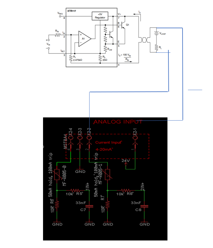
TIPD158: I find a mistake in Appendix A.1 Electrical Schematic
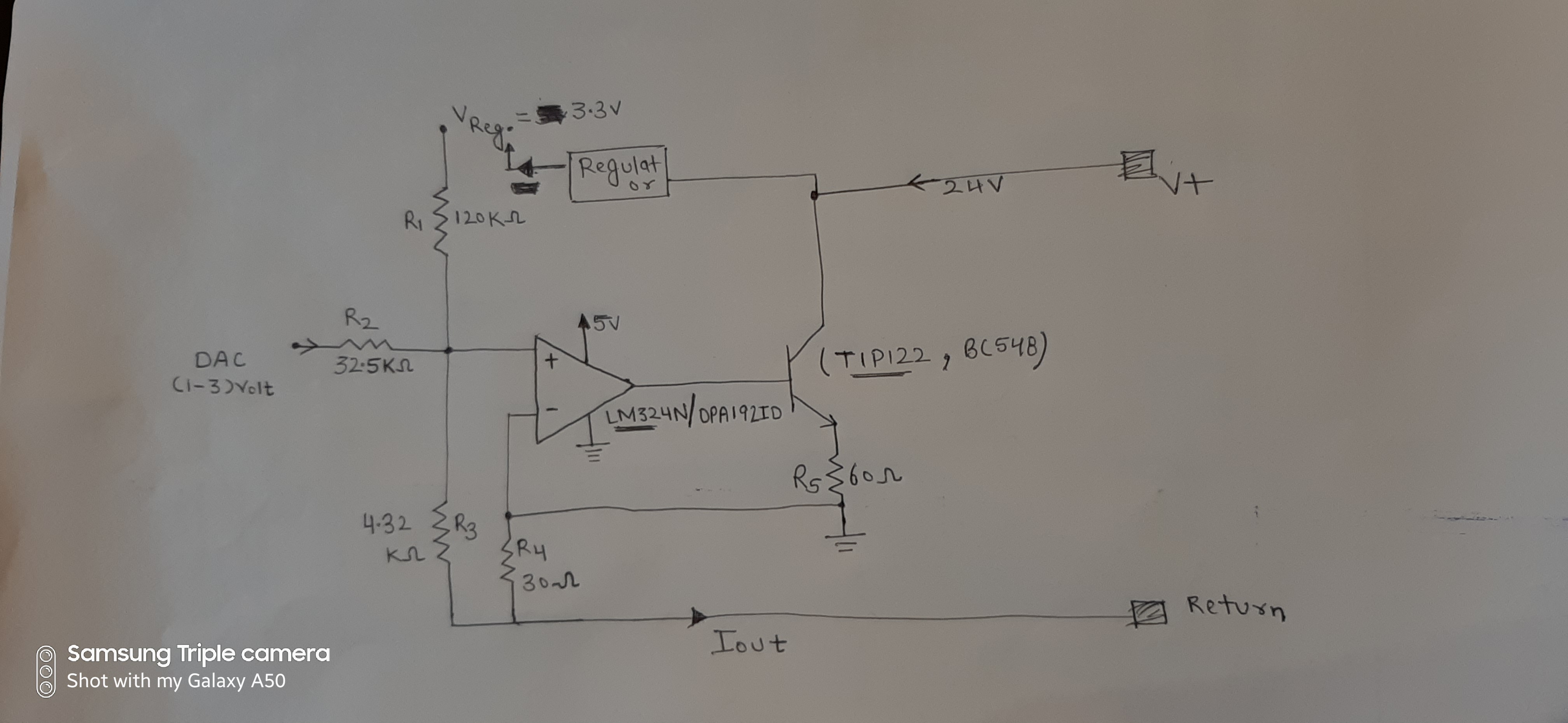
We are implementing the same circuit as given in TIPD158, but facing an issue of transistor's collector and emitter being shorted after giving 24 V loop supply on collector, and thus damaging the transistor and R5 in circuit attached.
the steps and points which we are following in our circuit are as follows-
1) We are giving input to opamp through R2 i.e. 1-3V
2) VReg supply coming through R1 from a regulator of 3.3V output.
3) the components used are
OPAMP- LM324n / OPA192ID
Transistor- TP122/ BC548
PFA the images attached as of implemented circuit as well as from TIPD158