This thread has been locked.

If you have a related question, please click the "Ask a related question" button in the top right corner. The newly created question will be automatically linked to this question.

ADS1220: NTC's affect for the input filter design.

Part Number: ADS1220

Hi team,

My customer want to use the ADS1220 to test the 4-wire NTC, the table shows the temperature and the resistor of NTC.

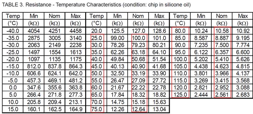
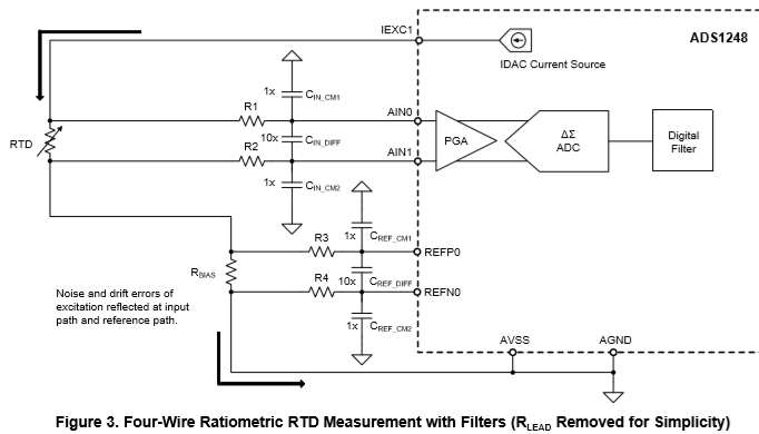
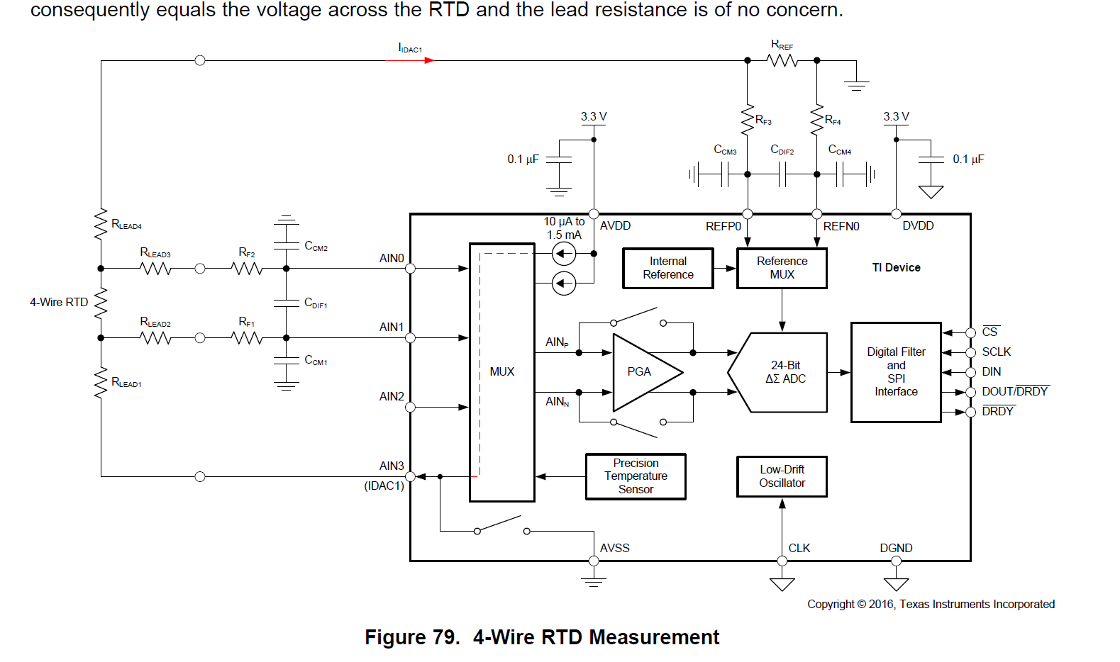
Can you help to comment, for this NTC, can I use the figure 79 circuit?

Will the NTC affect the design of the RC filter of the input and ref input?

Can I still refer to the description in the section 9.2.2.2 and 9.2.1 for the design of RF1, RF2, RF3 and RF4?

Lacey

Thanks a lot!

  • Hi Lacey,

    Is the temperature range of operation marked by the red boxes (25 to 125 deg C)? Within this temperature range the resistance values will range from about 100k to 2.5k. If you use IDAC excitation, then the total voltage drop of the lead resistances, sensor and reference must not be greater than AVDD-0.9V to meet the compliance voltage for the IDAC current source. The 2 lowest settings for the IDAC are 10uA and 50uA. 50uA will be too large a current when the resistance is 100k (100k * 50uA = 5V). So for this range of operation the current will be limited to 10uA.

    The reference voltage will need to be at least the same voltage as the maximum voltage of the sensor so that it can be measured. If the IDAC is 10uA and the thermistor ranges from 100k to 2.5k, the voltage of the sensor will range from 1V to 0.025V. So a 1V reference could be used with PGA enabled at a gain of 1. In this case the RREF value can be determined by 1V/10uA = 100k Ohm.

    The design would be similar to the 4-wire RTD design shown in the ADS1220 datasheet. The design description in section 9.2.2.2 is for a 3-wire design using 2 IDAC sources. In the 4-wire case only one IDAC source is used, so the calculations need to be adjusted for a single IDAC.

    The input filter calculations would follow the same as is discussed in the datasheet and SBAA201 application note.

    Best regards,
    Bob B
  • Hi Bob,

    According the application note, it require the filter resistor to be larger than the NTC's resistor and then the the filter resistor should be smaller than 20kohm

    Because the NTC's resistor of my customer is about 200k to 2k, so how can they choose the filter resistor.

    Please help to evaluate if the NTC's range can use the 4 wire RTD design?

    In addition, can you help to provide the impedance of the input pin?

    Lacey

    Thanks a lot!

  • Hi Lacey,

    The RTD application note is more of a thought guide of the process. The RTD in the application note won't be as large as the NTC. So if the values don't match with the application note that is ok. Just make the major consideration the cutoff frequency for antialiasing. Aliasing and filtering is discussed in the ADS1220 datasheet in section 9.1.2 on page 45.

    For the ADS1220 I can tell you for sure that the input leakage of the device will be the biggest factor. We don't specify the impedance for the device, but instead show input current. These graphs start on page 12 of the ADS1220 datasheet. The best inputs are AIN0/AIN1. AIN2 and AIN3 have higher leakage. AIN3 is made even worse due to the low-side switch. Due to the leakage I would suggest limiting the series input resistance to 4.7k or less to limit error from the leakage current. I'm sorry I didn't mention this at the beginning.

    Best regards,
    Bob B